UML Communication Diagram
Know it All about UML Communication Diagram
A Communication Diagram in UML visually represents the components of a system along with the interactions or messages exchanged between the object. It also shows the sequence of the messaging process; however, it is not similar to the interaction diagram entirely.
A communication diagram is an extension of an object diagram as it shows messages exchange along with the objects. Communication diagrams thus represent the associations among objects while showing the messages the objects exchange among them.
Though communication diagrams and sequence diagrams are not entirely similar, they have some standard features nevertheless. Communication diagrams and sequence diagrams show some standard set of information. However, one diagram conveys or emphasizes some specific information better than the other.
Communication diagrams have a free-form arrangement of objects or parts of a system. This is very similar to how classes and objects are arranged in class and object diagrams. The interactions between the objects or components of the system are shown in chronological order as they occur. Thus, you can place objects neat with the highest number of interactions between each other near one another. In this way, communication diagrams highlight the objects with the most number of communication with each other.
Communication diagrams have a significant advantage over other diagrams because they are much more space-efficient. They are also very effective because they highlight the objects that have the most extensive number of communication instances going on. Also, elements can be easily placed or erased in both horizontal or vertical directions. Finally, it is highly beneficial in agile technologies because modifications are relatively easy and needed frequently.
Communication diagrams are used for multiple purposes. Some of them are discussed below.
UML has a wide variety of diagrams, and each diagram uses a different set of notations or symbols. Therefore, it is essential to learn the other notations, particularly to communication diagrams, to make robust and effective diagrams. Communication diagrams have a few notations, including objects, links, and different types of messages that are the building blocks of any communication diagrams.
1、Objects
Objects can take different forms based on their role in the communication process. For example, they can be the sender or the receiver. Supplier objects supply the method that is called and therefore receives the message. Client objects call methods on supplier objects and therefore send messages.
2、Links
A link is a straight line that connects two objects and indicates a relationship between them. A link shows that the two objects can send messages to each other. Links are the elements that distinguish set communication diagrams from sequence diagrams. They offer the relationships between objects. If an object sends messages to itself, it is represented as a loop icon.
3、Messages
Messages in communication diagrams are represented as arrows from the Client object to the Supplier object. Messages express a client invoking an operation on a supplier object. Messages can be described as;
Different types of messages are:
In synchronous messaging, a sender transmits a message and must wait for a response before continuing. The symbol of this message is a straight line and a solid arrowhead.
In an asynchronous message, a sender does not need to wait for a response before proceeding. This type of message is represented by a straight line and a lined arrowhead.
Typically, the sequence of messages is shown by a number on the message. The number determines the chronological order in which messages should be read.
Here are the steps for the creation of communication diagrams in the premium drawing software EdrawMax. EdrawMax is a great tool to draw professional quality UML diagrams quickly and in less time.
If you want to create the communication diagrams from scratch, then follow these steps instead.
Step 1: Start the EdrawMax program.
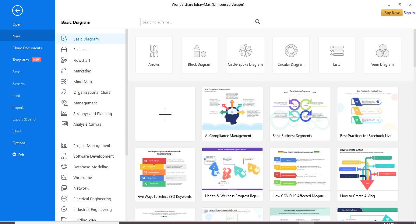
Step 2: Go to New>Software Development and select the UML modeling tile.
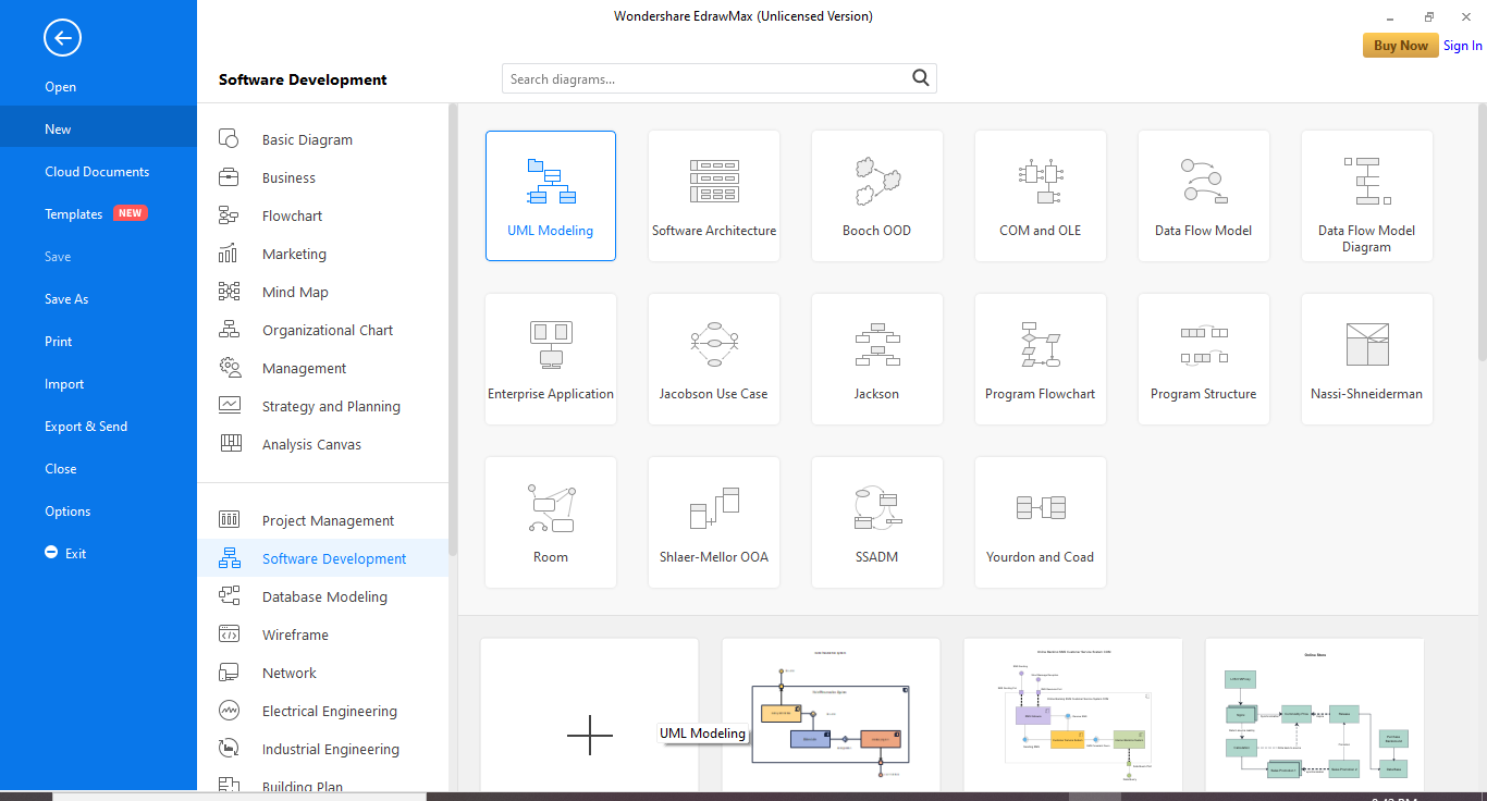
Step 3: Now, in the bottom pane, click the plus symbol tile.
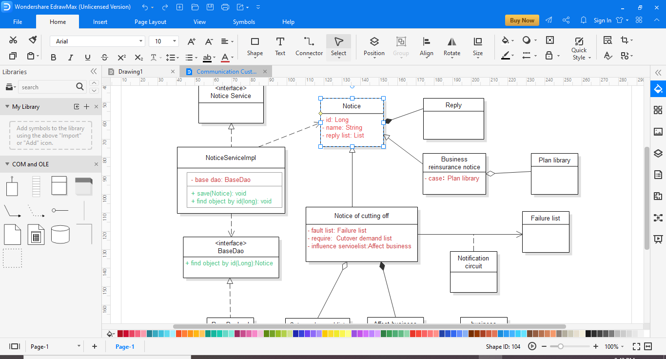
Step 4: You will have a canvas available on your screen. You can search the communication diagram symbols in the left pane.
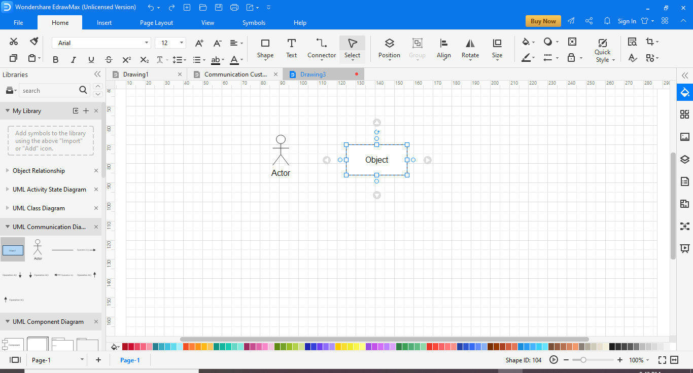
Step 5: Drag the required symbol on your canvas and create your communication diagram . Once you are done with the required modifications, you can save and export your document in multiple formats.

・ Simple alternative to Visio
・ 26k+ symbols
・ 10K+ free templates
・ 10+ AI diagram generators
While creating a communication diagram, you will be representing the logic for sophisticated procedure, function, or operation. A few general tips for a more functional communication diagram are;
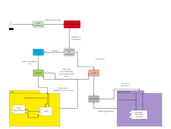
This is an example of a communication diagram that is representing an order placing use case. First, the end-user communicates with the login process, and based on its result, s/he is given access to product search, cart, and order placement process. Next, the system also communicates with the payment processing and inventory.


