- Part 1: What is Logic Diagram?
- Part 2: Purpose and Benefit of Logic Diagram
- Part 3: Symbols and Icons of Logic Diagram
- Part 4: What to Do Before Creating Logic Diagram?
- Part 5: How to Make Logic Diagram in Wondershare EdrawMax?
- Part 6: Tips for Making Logic Diagram
- Part 7: A Example of Logic Diagram
- Part 8: Conclusion
A digital circuit is designed in a way that it accepts two or more values as inputs that are either 0s or 1s, and produces one or more outputs that are again either 0s or 1s. The illustration that explains such an equation through graphical means is called a logic diagram. A full-fledged digital circuit uses gates that are electronic devices that produce a digital output as per their nature and the type of input they receive.
That said, in the following sections you will learn what a logic diagram is, why a digital circuit is important, how many types of gates are there, and how they participate in such an illustration.
Part 1: What is Logic Diagram?
As mentioned above, a logic diagram is a graphical illustration that shows how different types of gates are connected to form a digital circuit to perform a particular task. Another thing that is mostly used in conjunction with the logic diagrams is truth table. While the drawings demonstrate the gates and the way they are allied, the truth tables talk about the final outputs that the devices produce when the signals are sent to their input points.
Part 2: Purpose and Benefit of Logic Diagram
The purpose of a logic diagram is to predict the expected output according to the alignment of the gates. When read along with its corresponding truth table, the precise result can be calculated which, depending on the type of inputs the circuit has received, could be either 0 or 1.
The benefit of having a logic diagram is to eliminate the chances of financial losses, time wastage, and getting unexpected results that the engineers and designers may otherwise face without it. A logic diagram along with its truth table serves as a boon to calculate the exact output. If the technologists find any inconsistencies in the circuit, they could be corrected right on the paper before diving into practical implementation.
Part 3: Symbols and Icons of Logic Diagram
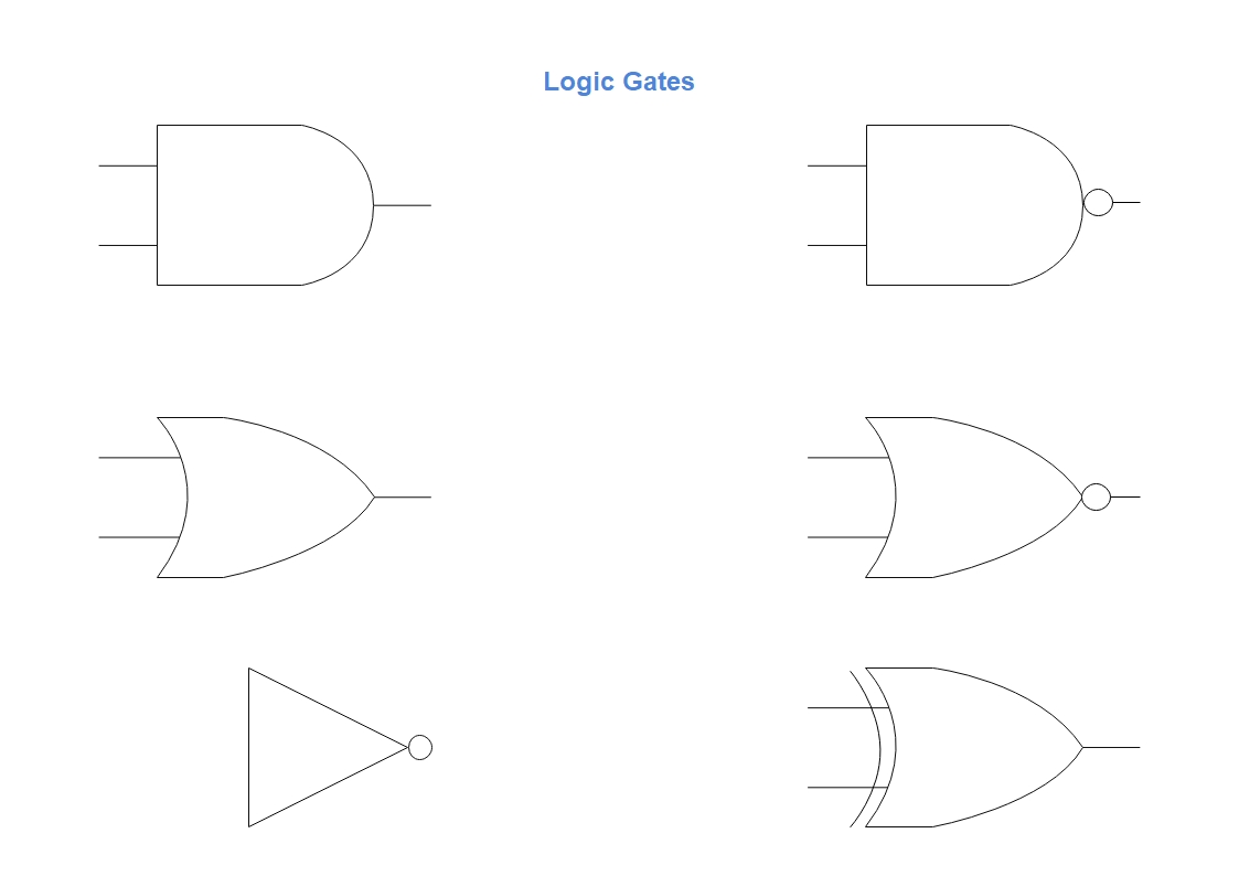
When symbols of a logic diagram are talked about, there are not many of them to work with due to the presence of fewer digital devices. However, when the digital circuits are coupled with other components, highly advanced electronic or electrical equipment can be produced to perform complex tasks.
Some of the most common icons that you will see in a logic diagram include:
Part 4: What to Do Before Creating Logic Diagram?
The fact is that if you are good at reasoning, it wouldn’t be challenging for you to create a logic diagram. Nevertheless, there are still a few things that you may want to consider before drawing a fully functional and reference-worthy illustration. Some of these points are listed below:
- Thorough Understanding of Gates
- Truth Tables
- Understanding of Circuits
- Use a Diagramming Tool
It is imperative to have an in-depth understanding of the logic gates and how they work. You must also know their symbols in order to prepare accurate diagrams.
You must also know how to create truth tables out of a logic diagram. This helps you assess the output, and will further enable to you finetune the illustration for better results.
In addition to having decent knowledge about the logic gates, you must also know how to design circuits. Placing the gates incorrectly or connecting them to the wrong analog components might result in severe damage to the device, financial loss, and/or injuries to the designers/engineers working on the project.
Even though you can draw a logic diagram on a large sheet of paper, it is advisable to use efficient diagramming software such as EdrawMax from Wondershare. Not only such a program will expedite your entire creation task, but it will also allow you to use the perfectly designed symbols from its library, thus eliminating your need of sketching them from the start.
Part 5: How to Make Logic Diagram in Wondershare EdrawMax?
As explained earlier, EdrawMax is an efficient diagramming tool to create illustrations. The application is suitable for almost all industry types including mechanical engineering, building constructions, software development, network infrastructure, and much more. You can follow the steps given below to learn how to make a logic diagram with Wondershare EdrawMax:
Step 1: Choose a Template
Launch Wondershare EdrawMax, when you are on the New category in the navigation bar, select the Electrical Engineering industry from the center pane. From the upper row of the right window, choose Circuits and Logic, and then click your preferred template from the lower section to open it in the canvas.

Step 2: Modify the Circuit
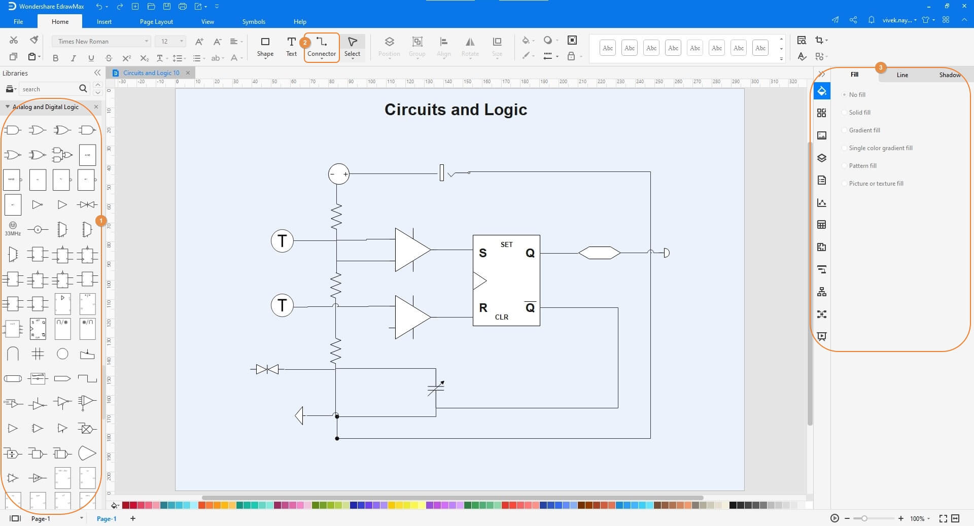
Drag more symbols from the libraries on the left to the canvas. Use the connector lines to connect the symbols of the devices to the existing ones to form a circuit. Although not necessary as the symbols of the logic gates are already self-explanatory, if need be, you can use the tools in the right pane to decorate the icons on the canvas. Note: It is highly recommended that you also prepare a truth table for the chart to ensure that the readers (engineers/designers) can predict the output easily.
Step 3: Save the Logic Diagram and Export
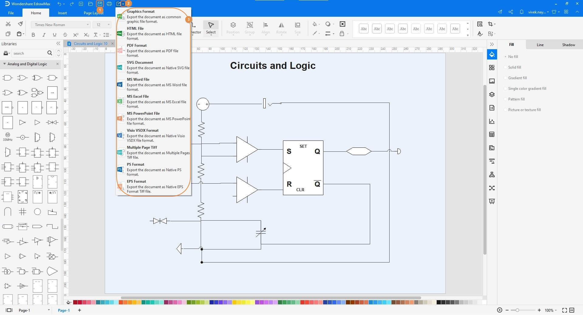
Once the logic diagram is drawn, click the Save icon from the top-left corner, and save the project to your local computer. Next, click the More button next to the Export icon, and when the menu appears, choose your preferred format to export the chart.
Part 6: Tips for Making Logic Diagram
Now that you know how a logic diagram works, what it is used for, and how it can be drawn, it is time to understand a few tips that would surely come in handy in preparing a professionally acceptable chart. A couple of such points that are worth remembering include:
- Because the symbols of many gates closely resemble each other (e.g., ‘AND’ and ‘NAND’), you must draw large and clear icons in the diagram so the difference is easily identifiable
- Leave some space on the canvas/chart for the truth table
- While explaining with an example, consider representing the input points with A, B, C, etc., and the output with Y
- Always remember that both the input and output can be either 0 or 1, and there could be no other value apart from these two whatsoever
Part 7: A Example of Logic Diagram
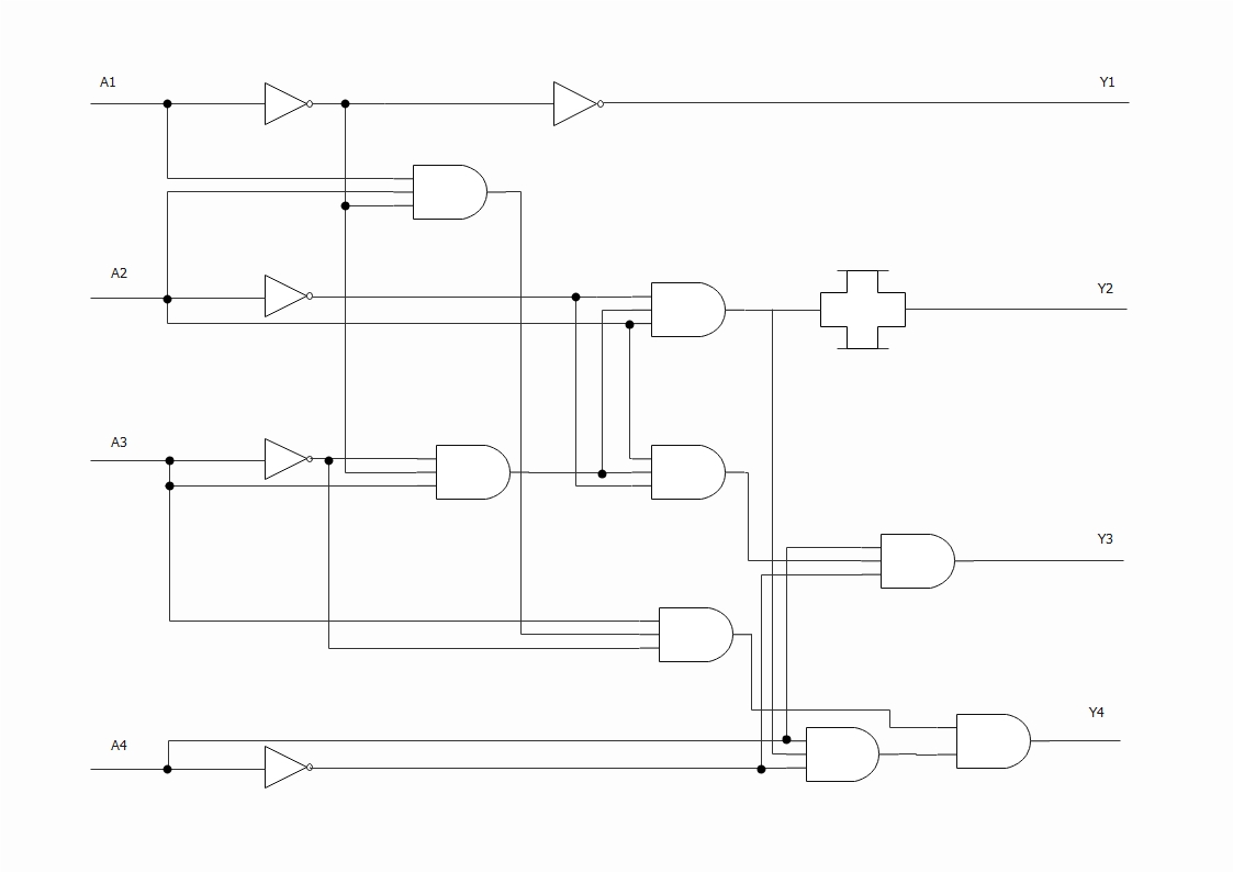
The above logic diagram is an example of a complex digital circuit where a couple of NOT gates and a few AND gates are connected. The illustrated circuit is designed to accept four inputs namely A1, A2, A3, and A4, and is expected to produce four outputs namely Y1, Y2, Y3, and Y4 in return. When the signals are sent to the input points, they pass through the logic gates, and according to the type of input values (0 or 1) and the gates, the output is produced.
Part 8: Conclusion
A logic diagram shows how multiple gates are connected to form a digital circuit that is further expected to perform a particular task. While understanding the symbols and their uses is simple, it is highly recommended to use efficient diagram software like Wondershare EdrawMax to prepare the vector illustrations in order to make them look professional and globally recognizable.
