What is UML | Unified Modeling Language
- What is UML?
- The Origin and History of UML
- Object-Oriented Concepts Used in UML
- What is a UML Diagram?
- UML vs ER Diagram
- Types of UML Diagrams
- Free UML Diagram Templates
- Key UML Diagram Symbols
- How to Draw a Wiring Diagram?
- How to Start a UML-Based Development Project?
- How to Create a UML Diagram Easily?
What is UML?
The Unified Modeling Language (UML) is a language used in the field of software engineering that represent the components of the Object-Oriented Programming concepts. It is the general way to define the whole software architecture or structure.
In Object-Oriented Programming, we solve and interact with complex algorithms by considering themselves as objects or entities. These objects can be anything. It can be the bank or a bank manager too. The object can be a vehicle, animal, machine, etc. The thing is how we interact and manipulate them that they can perform tasks and they should.
The tasks can be interacting with other objects, transferring data from one object to another, manipulating other objects, etc. The single software could have hundreds or even thousands of objects. So, UML provides us a way to represent and track those objects in a diagram to become a blueprint of our software architecture.
The Origin and History of UML
The concept of UML was first developed at Rational Software in the late 1900s between 1994 and 1995. In 1997, a significant thing recorded as the Object Management Group (OMG) adopted UML as a standard to meet before developing a new system. The purpose of UML these organizations set is.
- The UML will provide software developers a blueprint and other tools for analyzing and designing the software architecture. It will also model business and other similar processes.
- It would pave a meaningful way to exchange information about the model between different tools, and a contract on explanation would be made.
UML 1.x
The UML is evolving ever since its concept was made. In 1996, UML Partners was organized by Rumbaugh, Jacobson, and Booch to complete the formalities and specifications of the Unified Modeling Language (UML), and finally, in 1997, they published the UML 1.0 draft. It contains some lackings, so different versions were made after this, like UML 1.2, 1.3, etc.
UML 2.x
The current UML the world is using is UML 2.x. In 2005, the UML 1.5 was replaced by the UML 2.0, the more developed and advanced version of its predecessor. However, after this, many versions were released, like 2.1.1, and 2.1.2, etc. The current and more advanced version we are using is UML 2.5. It contains more features than the UMLs before.
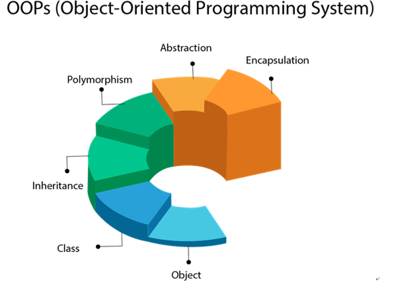
Object-Oriented Concepts Used in UML
Before understanding UML, you should know what Object-Oriented Programming and its concepts are. The six main concepts of Object-Oriented programming concepts are.
Classes
The classes are the data structures that contain the properties, attributes, constructors, or methods. Consider it as a container. The class is also called a blueprint.
Objects
The objects are the real-world entities that the programmers deal with to solve real-world problems. The object can be anything from a human to a building, etc.
Inheritance
Inheritance is the word that we all are familiar with it. Inheritance in OOPs makes you inherit a sub-class from the superclass. When you inherit a class from the superclass, you can access the superclass properties, constructors, methods, and objects besides the properties or methods private to the superclass.
Abstraction
Abstraction makes you hide the details of functionalities of a class from a user. In abstraction, you initialize methods in an abstract class and define those methods in the inherited sub-class.
Encapsulation
Encapsulation makes you provide security to your properties and methods from the outer world. You define encapsulation by making getter and setter methods.
Polymorphism
"Poly" means "many," and "mor" means "form or face." Binding together makes "many forms.” Polymorphism makes you make many attributes and methods from a single method or attribute in a class by method overloading and method overriding concept.
Source: francescolelli.info
What is a UML Diagram?
A UML diagram shows the unified visual presentation of the UML (Unified Modeling Language) system intending to let developers or business owners understand, analyze, and undertake the structure and behaviors of their system.
So far, the UML diagram has become one of the most common business process modeling tools, which is also highly significant to the development of object-oriented software.
Why Use UML Diagrams?
UML diagrams have many benefits for both software developers and businesspeople, and the most key advantages are:
- Problem-Solving - Enterprises can improve their product quality and reduce cost especially for complex systems in large scale. Some other real-life problems including physical distribution or security can be solved;
- Improve Productivity - By using the UML diagram, everyone in the team is on the same page and lots of time are saved down the line;
- Easy to Understand - Since different roles are interested in different aspects of the system, the UML diagram offers non-professional developers, for example, stakeholders, designers, or business researchers, a clear and expressive presentation of requirements, functions and processes of their system.
Usages of UML Diagrams
The diagram can be used in many different fields including software engineering or business processes to strengthen efficiency.
- Draft the System- In this case, the UML diagram is used by the development team to discuss the outlines and structure the overall system. This may include the forward design and the backward design for different activities, roles, actors, and so on;
- Visualize Programming Language - Different types of UML diagrams in a certain system can be translated into code directly to save time for software or related application development;
- Business Analysis - In reality, the UML diagram can also be used to analyze the business sales pathway in order to improve customer service;
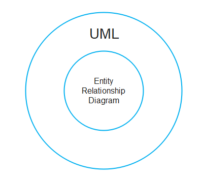
UML vs. ER Diagram
The main differences between the UML diagrams and ER diagrams are listed below.
| Full-Form diagrams | Unified modeling language (UML) | Entity Relationship Diagram (ER) |
|---|---|---|
| Definition | The UML diagram is a general-purpose way to visualize the main concepts of object-oriented concepts used in the software. It is the blueprint of the software architecture. | The ER diagram is the pictorial representation of the objects and their relationships. |
| Relationships | The UML diagram is the superclass of the ER diagram. | The ER diagram is the subclass of the UML diagram. |
| Usage | It is used to design the whole software architecture and to track it. | It is used to design and implement the databases. |
Types of UML Diagrams?
The two most main categories of UML diagrams are the Structure UML diagram and the Behavioral UML diagram. Furthermore, 14 sub-types of UML diagrams are divided into these two groups and each one of them has a different purpose. Now let's check out all of them in more details as shown below. You can also click on them to see more and download these examples for free.
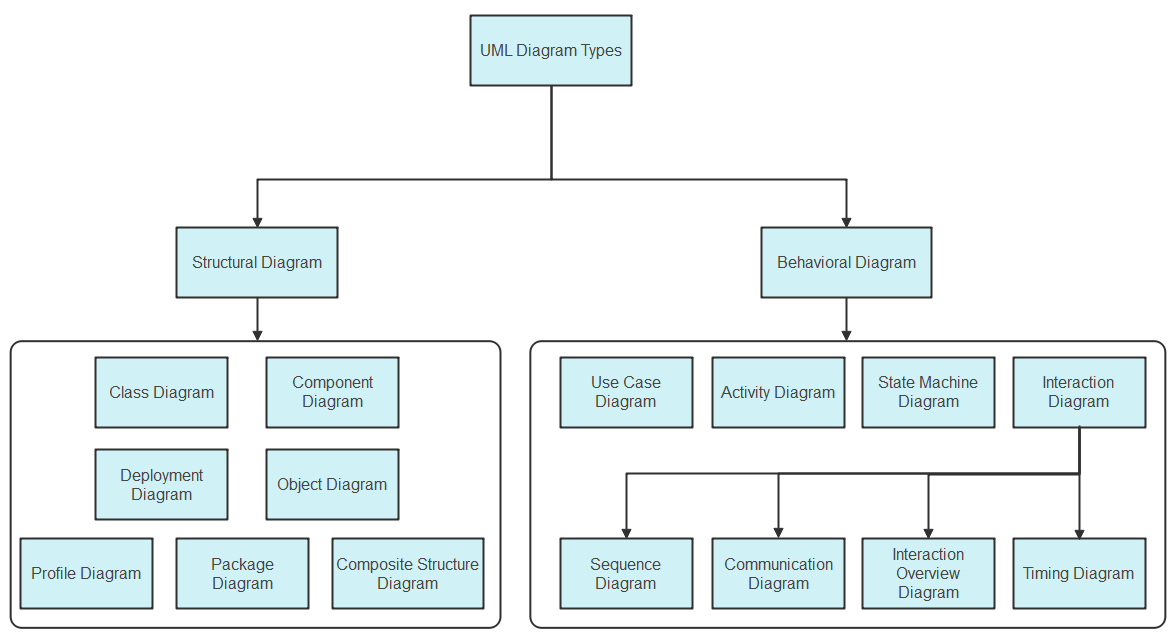
Structure Diagrams
These diagrams show different objects and the static structure of the system. The elements in a structure diagram may include abstract and some other related implementation concepts. This category has six sub-types:
- Class diagram
- Composite Structure diagram
- Object diagram
- Component diagram
- Deployment diagram
- Package diagram
- Profile Diagram
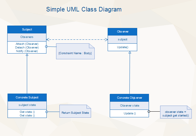
Class Diagram
It is the most widely used UML diagram sub-category. The class diagram is the building block of all object-oriented software systems. Users can depict the static structure and identify classes relationship of a system by checking system's classes and attributes. Each class has three basic elements: the class name at the top, the class attributes in the middle, and the class behaviors at the bottom. In reality, you can create classes such as "Sales Account" or "Online User" in business systems, or "Teacher" and "Student" in academic systems.
Composite Structure Diagram
Composite Structure Diagrams are used to show the internal structure, the behaviors of classifiers, and the relationships between classes in a system. The composite structure type is similar to Class diagrams but the former ones represent more detailed individual parts rather than the whole system structure.
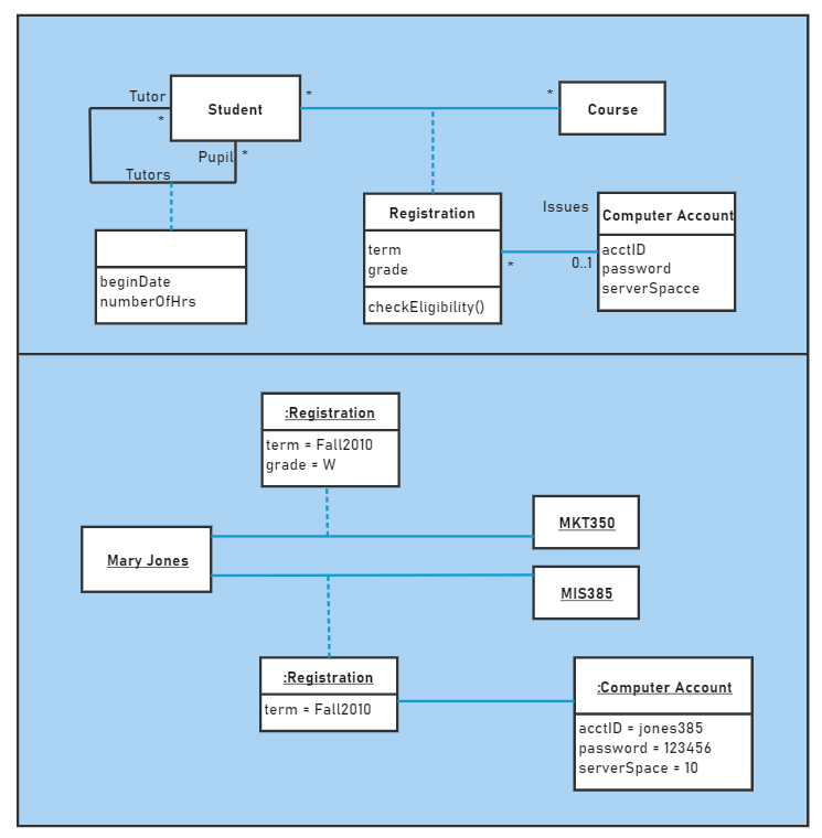
Object Diagram
Object Diagrams can be considered as the screenshot of the instances and their internal relationships in a specific system. By using such diagrams, developers can be able to analyze the operations of the system at a particular instant, and check their abstract structure. Furthermore, the relationship between a Class and an Object in software development can be described as the relationship between, for example, the class "Food" and the brand "KFC" or the general class "User" and a specific username called "David" or what else.
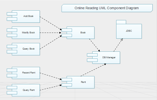
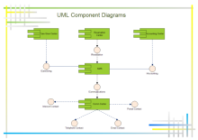
Component Diagram
Component Diagrams are used to show in what way the physical components in a system is organized. Normally, developers use the Component Diagram to check out implementation details, break down the system into smaller parts, depict the structural relationship between system elements especially in the case of large-scale complex projects with more advanced technologies.
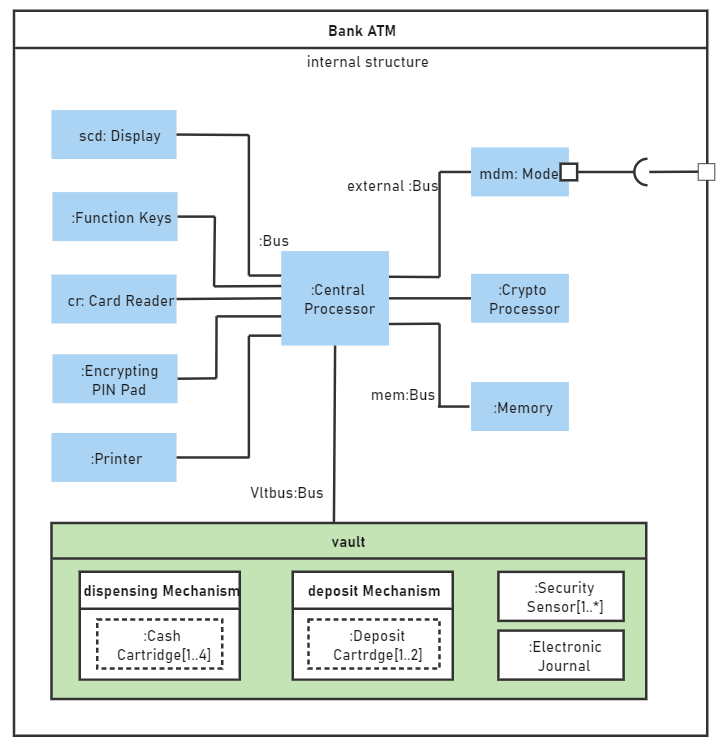
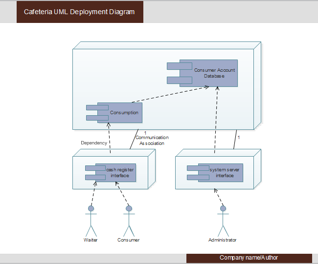
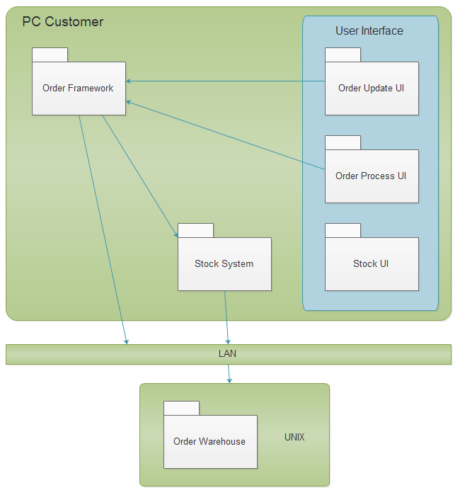
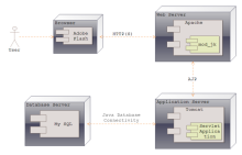
Deployment Diagram
Deployment Diagrams are generally used to show users the visual relationship between software and hardware. A sample Deployment diagram in the software development field has two main parts: Nodes (basically different kinds of servers) and Artifacts (normally client or database schema). Nodes host the Artifacts, while different types of Artifacts operate on Nodes.
Package Diagram
In general, Package Diagrams are used to depict how packages and their elements are organized into meaningful groups in a system. More specifically, Package diagrams can be considered as a structure that includes many deployment diagrams with nodes and artifacts. So far, package diagrams are used to organize the Class and Use Case diagrams.
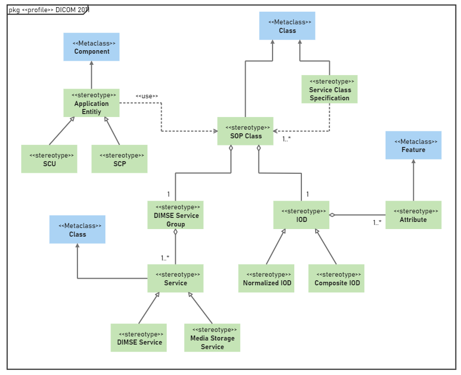
Profile Diagram
The profile diagrams are an extension of Unified Modelling Language (UML), which are a structural diagram that use stereotypes, tagged values and constraints to extend and customize UML.
Object diagram vs. Class diagram
The object and class diagram share the same concept but yet they have a difference.
The class diagram is a diagram that represents the structure of classes in the software. This diagram represents what the class contains and how they are interacting with other classes in the software. The class diagram shows the relationship between different classes in the software architecture.
But, the object diagram shows the properties of objects, how they are interacting with other objects, how they're using different methods of classes to communicate with other objects of the class. The class diagram is all about classes, and the object diagram is all about the objects.
Behavior Diagrams
These diagrams display the dynamic behaviors or in other words, what should happen in a system. For example, the way that objects interact with each other, or a set of changes to the system over a certain period. This category has seven sub-types:
- State Machine diagram
- Activity diagram
- Use Case diagram
- Sequence diagram
- Communication diagram
- Timing diagram
- Interaction Overview diagram
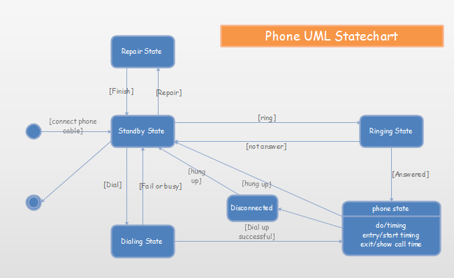
State Machine Diagram (State Machines or State-chart Diagram)
Such UML diagrams are used to represent the condition of the system, the dynamic action (different states) of a class in response to a particular time based on internal or external factors. A real-life example of the State Machine Diagram could be playing Poker cards. The final result (different states) of the game can be different based on players' specific strategies.
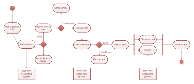
Activity Diagram
Activity Diagrams are used to illustrate the interconnected flow of different activities and actions (both in sequential form or in parallel type) in a system, and to display the steps involved in the execution of a use case. This type of UML diagram is widely used both in business modeling process and software development.
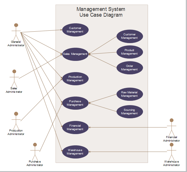
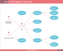
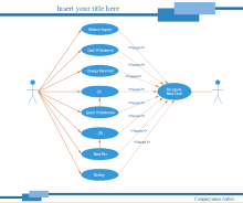
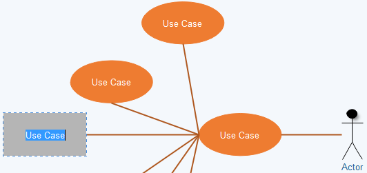
Use Case Diagram
A Use Case Diagram can be regarded as a good starting point for discussing project key actors and processes without going into too many implementation details. This UML diagrams is also the most popular type of the Behavioral UML diagram category, and is used to analyze the functionality (the use cases) and the interactions with different types of agents (actors) of a system. For business cases, enterprises may use such diagrams to check out the customer order system by monitoring the stock, product quality and so on. For daily life cases, Use Case diagrams are similar to the Hot Sale product list of your local supermarket. You know the product name and its prices according to the list when making your purchasing decision.
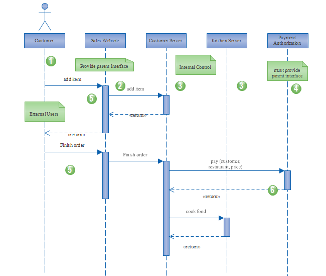
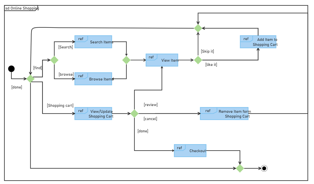
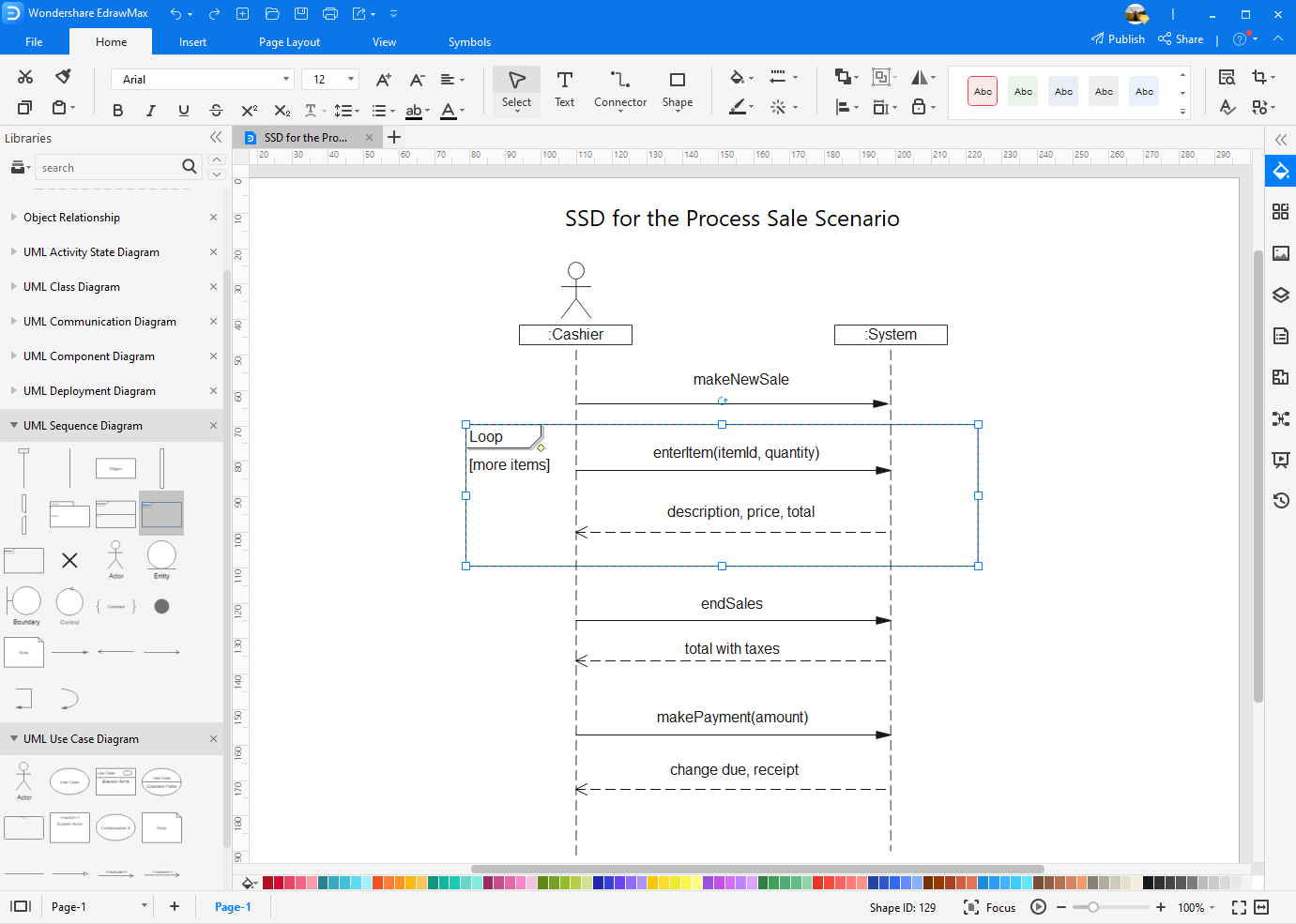
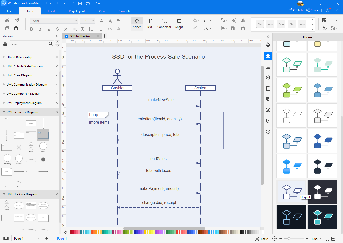
Sequence Diagram
A Sequence Diagram generally shows the interaction between objects in a sequential order. It is for users to document and understand requirements in a new system. In software development, this type of diagram is used to represent the architecture of a system.
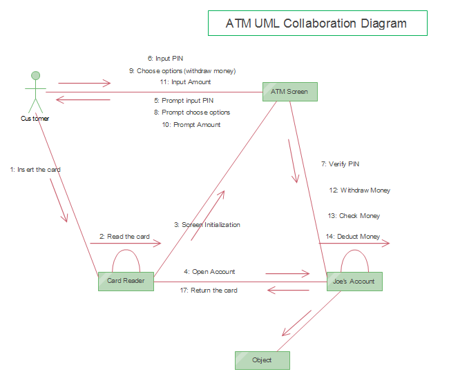
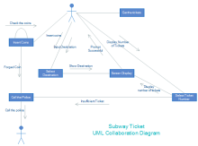
Communication Diagram (Collaboration Diagram)
A Communication Diagram is used to display sequenced communications between objects with the focus on primary objects and their relationships. Communication diagrams usually use number schemes and pointing arrows to show message flow. Moreover, compared with sequence diagrams, communication diagrams are much easier to be designed, but contains fewer details when drafting documentation for systems.
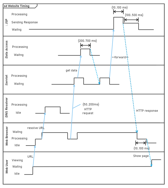
Timing Diagram
A Timing Diagram is a special form of the Sequence diagram that is used to show the behavior of objects over a certain time constraint. It is similar to the form of, for example, the history of iPhone development, or the growing trend of an international enterprise.
Interaction Overview Diagram
An Interaction Overview Diagram displays a sequence of behaviors and helps users simplify complex interactions (rectangular frames) into simpler forms in a system. It can be considered as a mixture of specialized activity and sequence diagrams, but Interaction Overview diagrams have more elements than Activity diagrams such as interaction, time constraint and more.
Activity diagram vs. Sequence diagram
The activity and the sequence diagrams are one of the types of the behavioral UML diagram and have a big contrast.
The Activity diagram shows us how the activity would be performed by each software component step-by-step. Plus, the communication of activities is also shown.
In the Sequence diagram, the objects and their correct order of performance are shown. Their performance is triggered when some events occur, but all objects work in a sequence form.
EdrawMax
All-in-One Diagram Software
- Superior file compatibility: Import and export drawings to various file formats, such as Visio
- Cross-platform supported (Windows, Mac, Linux, Web)


Free UML Diagram Templates
Here are free-downloadUML diagram templates for you to easily understand all of these UML sub-categories. All of these are editable with EdrawMax. Click on any of them to see more details.
|
|
|
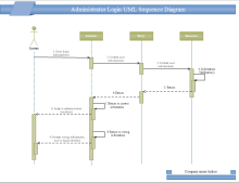
| Student Management Use Case Diagram | UML Sequence Diagram Template | Bank System Use Case Template |
|
|
|
| UML Component Diagram Template | Ticket UML Collaboration Template | Deployment Chart Template |
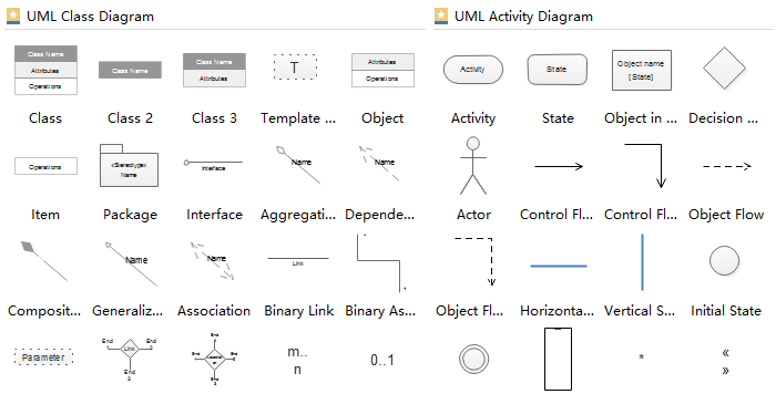
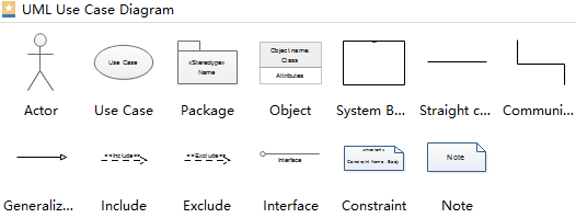
Key UML Diagram Symbols
There are many UML diagram symbols in each of the UML categories. Among all of these symbols, the Class diagrams symbols (defining attributes and operations of classes), the Activity diagram symbols (used to show states and activities) and the Use case diagram symbols (shown with different types of arrows) are the most popular ones.
How to Start a UML-Based Development Project?
The process to start a UML-based development project is quite simple.
Finding what you have to make
The first thing you have to do is to find what you are developing. What kind of software is this? What would be its functionalities? What a user expects from this software.
Planning about your software
After knowing what your project is all about, get into the internal structure of the software. Calculate what type of classes you would include in the project. These classes contain properties, constructors, methods. How many objects would be there? How will the classes interact with each other? It is very complex work, so it's best to consult a software developer to plan your software architecture.
Making a UML Diagram
Now, after calculating the internal structure. Get the software to design your UML. You can't do it on paper with a pen or pencil. You can do it on EdrawMax that is the best-known diagram-making software. Use all the concepts of UML to make your UML diagram. See, how would you connect inherited classes, or how would you connect the property of a class used by the other class. Check if you are making a structure of the software or defining the behavior of your class, methods, objects, etc., then decide what type of UML you have to make, either structural UML diagram or behavioral UML diagram. Get training for making a UML.
Developing your project
Then finally start to develop the project. If you find any lacking, then don't worry. You have a UML. Use it and add your extensions. Track your project with the help of UML.
How to Create a UML Diagram Easily?
Picking up an easy-to-use UML diagram maker is important for everyone who wants to create a professional UML diagram. Luckily, EdrawMax is one of the most versatile UML daigram creators. Simply follow these steps to quickly create a professional-looking UML diagram.
Step 1: Open a preset UML diagram template or a blank drawing page for your work. Double-click one of the icons in the UML Model Diagram category to start creating.
Step 2: Drag and drop UML standard shapes from the built-in libraries. Adjust the shape size to fit the drawing board.
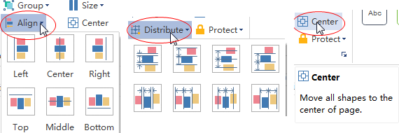
Step 3: Align or group UML shapes for the appropriate locations.
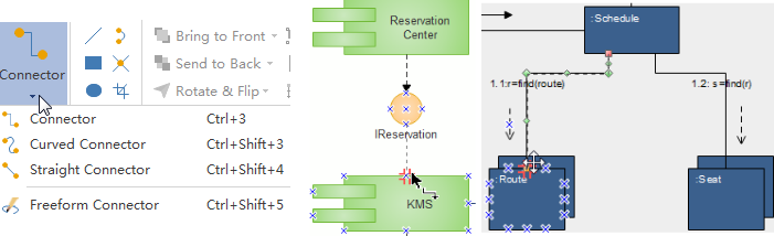
Step 4: Connect UML shapes by adding more connection points on the shapes or by using the preset relationship lines.
Step 5: Double-click to edit default shape text.
Step 6: Further format your UML diagram by changing the colors of shapes/lines, trying different diagram theme and adding background etc.
Step 6: Print, save to built-in personal/team cloud, or export to different formats including Visio, MS Office, PDF and more.
Create Your Own UML Diagrams Right Now!
Simply use EdrawMax for efficient UML diagramming. Enjoy Edraw's polished drawing board, extensive UML shapes built-in library, quick-exporting options for a wide range of formats including Visio, preset team and personal cloud account for your communications and the convenient drag-and-drop editor. Explore more features by clicking on the free download button at the end of this page.