What is an Entity Relationship Diagram (ERD)? - All You Need to Know
Contents
- What is an Entity Relationship Diagram (ERD)?
- ERD Background Overview
- Basic ERD Elements
- Major ERD Cardinality Classifications
- Key ERD Symbols
- ER Diagram Data Models
- ERD Applications
- Limitations of ERD
- Relationships among ERD, DFD and BPD
- More Free ERD Templates and Examples
- How to Create an ERD?
- Further Reminders of Creating ERDs
- How to Draw an ERD with Software?
What is an Entity Relationship Diagram (ERD)?
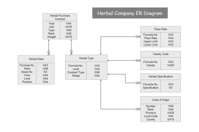
An Entity Relationship Diagram (ERD) shows how entities (such as people, objects or concepts etc.) relate to each other in a particular system. Generally, an ERD does not define business processes, but graphically displays business data patterns. In this case, the entity can be regarded as a noun and the relation can be considered as a verb. ERD can help users conceptualize abstract elements in order to discuss and understand the relationship between different concepts. The simple ERD example below shows you the database system of a herbal company. Feel free to click on it to see more.
ERD Background Overview
In fact, the study of the relationship between different objects can be traced back to some ancient Greek philosophers. By the 1970s, data modeling had become very popular, but there was no universal and effective method to standardize it. In 1976, Peter Chen, who taught at Massachusetts Institute of Technology (MIT), first introduced the entity relationship model in his paper and designed corresponding charts for his findings. Peter was inspired by the data structure diagram (Bachmann diagram) proposed by Charles Bachmann in 1960s. Later, Charles Bachman and James Martin made improvements to the basic principles of ERD, which also promoted the development of the Unified Modeling Language (UML) diagram in computer science.
Learn about EER Diagrams and the differences between these 2 diagrams.
ERD Basic Elements
Most ERDs have evolved from the design of physical databases. Don't worry about their complexity, you can easily learn this field by checking out the following three basic ERD elements:
Entities
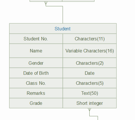
Entities are usually divided into five categories: concepts, locations, roles, events, and things (people, places, events, sales, customers, company departments, students, or products etc.). An entity is shown in a database table in a data system, and each row of the table represents an instance of the entity. For example, the Name entity in the table below could be Jack, Alice and so on.
The most common subtypes of ERD entities are:
- Weak Entities, which are depended on the existence of another entity. For example, an order item will be meaningless if there is no order.
- Strong Entities are defined without relying on other entities.
- An Entity Set is defined as a type of entity at a specific time period (e.g. the purchased customers in the 3rd week etc.).
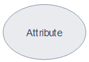
Attributes
Attributes are the detailed information collected for entities (including the characteristics of the data etc.). In a school management system, the attributes of students can be their names, family addresses, classes and contact phone number and so on. The attributes of job hunters can be their age, previous position, and location etc.
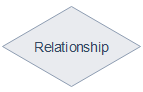
Relationships
Relationships describe how entities interact with each other. Besides, relationships are usually marked with verbs, for example, a customer buys software online. In addition, if an entity connects the occurrences between two different entities, then it is called a recursive relationship. For example, a department manager may be the supervisor of his subordinates, or one of the subordinates of his supervisor.
ER Diagram Major Cardinality Classifications
There are three main types of relationships between entities:
One-to-one
An instance of the entity A is associated with another instance in the entity B. For example, an enterprise employee has an unique company ID number.
One-to-many
An instance of the entity A is associated with one or more instances of the entity B, but not vice versa. For example, the marketing department may have many employees, but each marketing department employee usually corresponds to only one department: the marketing department. An order number usually has only one corresponding purchaser, but a purchaser can have more than one order number of the ordered products. Here is another example that shows you a product can have a series of unique entities including the Product No.
Many-to-many
An instance of the entity A is associated with one or more instances of the entity B, and vice versa. For example, a freelancer may offer part-time services to several companies, meanwhile the company may also cooperate with different part-time workers.
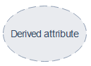
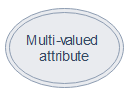
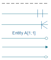
Key ERD Symbols
Typical ERDs usually have the following symbols:
ER Diagram Data Models
ERD usually has the following presentations: the conceptual data model, the logical data model, and the physical data model. Although these three forms all contain entities, relationships and attributes, they are used by different groups of users. Normally, business analysts prefer to use the conceptual and logical models, while database engineers like using the logical and physical models.
Conceptual Data Model
This ERD model lacks specific details, and it only contains the definition and general tables of the entities in a data system. The conceptual data model provides an overview of your project scope and the general architecture of the system, and show how data sets are related to each other. However, for smaller systems, it may not be necessary to draw such a model.
Logical Data Model
This ERD model is more detailed than the conceptual data model because the former type contains detailed attributes of entities and relationships between different sets. The logical ER model is also developed independently of a specific database management system.
Physical Data Model
The physical data model assigns more detailed technical details to each entity and it offers users with guidance on how to construct their systems and associated data. Physical data models are usually based on logical data models.
ERD Applications
Since ERDs are easy to understand even for non-professional or non-technical users, they are widely used in the following fields:
- Design and troubleshooting of software and computer databases - ERDs can be used to model data architecture for information systems at the early stages of software planning.
- Scientific researches - ER diagrams can also be used to study a large number of complex scientific data sets or structured data sets.
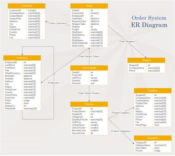
- Business Information System - ERD can also be used to design or analyze data in business processes, such as sales figures, to simplify processes and improve efficiency. In addition, developers, designers and customer service teams can use ER diagrams for effective team communication.
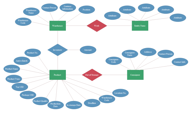
Here is an ERD example that shows a customer order system of a trade enterprise. You can click on it to free download its PDF version.
Limitations of ERDs
The limitations of ERD mainly including the following aspects:
- ERDs are not suitable for systems that contain unstructured or semi-structured data sets. This may be due to the lack of support for data integration.
- It can be difficult to integrate an ERD with an organization's existing database due to different data architectures.
Relationships among ERD, DFD and BPD
In practice, ERDs can also be used in combination with other related database diagram types such as:
- Data Flow Diagram (DFD) - DFD can be used with ERD to analyze a system, visualize the information flow in the process of the system, and check the data operation status of the system.
-
BPMN Business Flow Diagram (BPD) - BPD can also be used with ERD to visualize business processes in order to display and analyse the overall structure of a data system.
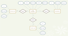
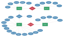
More Free ERD Templates and Examples
Free download these ERD templates below for your projects. Click on any of their names to see more details.
|
|
|
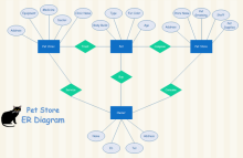
| Faculty Info ER Diagram Template | Storage ER Diagram Template | Pet Store ER Diagram Template |
|
|
|
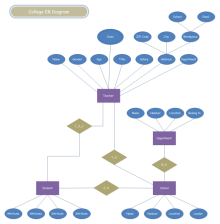
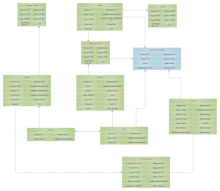
| College System Template | Course System Template | Blended Model ER Diagram Template |
How to Create an ER Diagram? - a Simple but Widely Used Guide
Drawing an ER diagram is not complex if you do the following easy steps:
Step 1: Define your Purpose and Scope
Do you need an ERD for your business process, or to develop new software databases? Depending on the actual needs, as mentioned earlier, you may need to draw a conceptual, logical, or physical model.
Step 2: Add Entities
Add and name your entities correctly. You should also check out whether the tables in your ERD are sufficient to store enough data. Add or subtract your entity tables accordingly.
Step 3: Decide and Insert Your Attributes
In this step, you should decide your entity attributes and give meaningful and understandable attribute names.
Step 4: Determine the Specific Relationships
Now, you should determine and label the specific relationship type for each of your connections (one-to-one, one-to-many, many-to-many). Don't worry about isolated entities (though this is not common).
Step 5: Review your ERD
Reduce data redundancy by restructuring entities, and check for missing important entity details. You can also split complex data into separate entities.
Further Reminders of Creating an ER Diagram
- Singular nouns are commonly used to name entities. However, sometimes you may need to use different adjectives to distinguish similar entities, such as full-time and part-time employees.
- Use color to distinguish entities and highlight key areas in your ERD.
- Keep in mind that an individual entity should appear only once in a particular ERD.
- You can extract keywords directly from your business process documents or product requirements files to be used in your ERD.
- In the process of mapping and modeling, you need to communicate with your key team members (e.g. business experts, senior R&D staffs etc.) regularly on how to fulfill the business requirements in your database model. This will help to adjust the system in time according to actual improvements.
How to Draw an ERD with Software?
There is one free ERD software that can satisfy your needs and help you create ER diagrams quickly with ease.
The process is even easier than you thought. Just try the following quick steps.
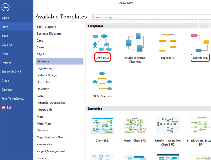
Step 1 - Start the ERD Software
Start EdrawMax and go to "Available Templates" - "Database", double-click to open a new drawing page. Alternatively, you can select one of the preset templates for your work.

An all-in-one platform for 210+ diagrams.
・ Simple alternative to Visio
・ 26k+ symbols
・ 10K+ free templates
・ 10+ AI diagram generators


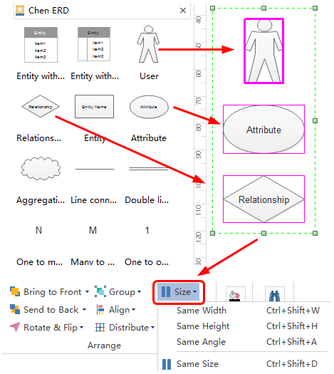
Step 2 - Add Editable Elements
To get the symbols, simply click Library button on the top left corner under the Ribbon, and navigate ERD and database symbol category. Next, drag and drop the built-in ERD shapes from the left-hand library to the right-hand canvas for further customizations, such as changing sizes/colors, or group a set of your individual entity shapes.
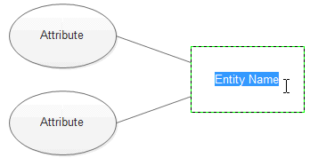
Step 3 - Edit Text
Double click on the default text to edit your own words.
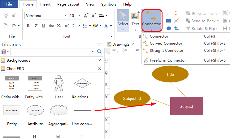
Step 4 - Connect Your Entities
Connect your individual entities by inserting straight connectors. Alternatively, you can drag and drop different styles of ERD connectors from the left-hand preset libraries.
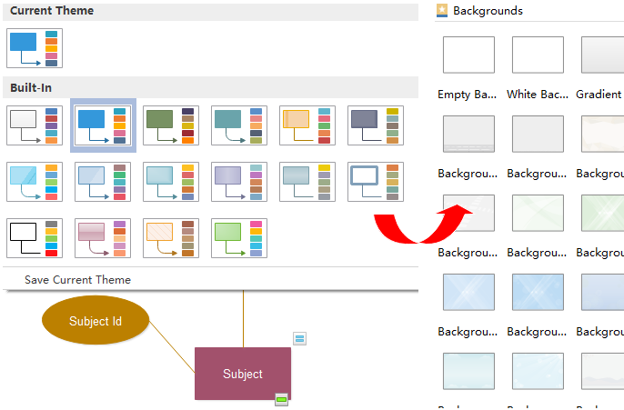
Step 5 - Apply a Theme to Your ER Diagram
It's easy to change the whole ER diagram's theme, shadow effects and background based on the built-in auto-create tools.
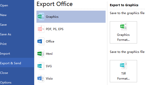
Step 6 - Save/Print/Share/Export
Once done your work, you can save it on the Edraw team or personal cloud, print it in different paper sizes including A3 and A4, one-click share it on your social networking platforms, or export it to a wide range of different formats such as JPG, PDF, MS Word and more.
Drawing Your Own ER Diagrams with EdrawMax
Now, you have learned all the key aspects of the ERD. It's your turn to simply create your ER Diagrams with the cross-platform EdrawMax! Conveniently craft visually engaging diagrams by using the preset standard ERD symbols and auto-create tools. Feel free to drag and drop built-in shapes, quickly connect your entity boxes, change the default diagram theme and do more with the software. Save and share your files on the Edraw team or personal cloud for your collaboration. Have a try right now by clicking on the Download PC Version or Mac Version button at the end of this page!


