How to Read Circuit Diagrams
Learning to read electrical schematics is like learning to read maps. Electrical schematics show which electrical components used and how they are connected together. The electronic symbols consisted represent each of the components used. The symbols are connected with lines.
Recognizing Electrical Schematic Terms
Here are some of the standard and basic terms of circuit diagrams:
- Voltage: Voltage is the "pressure" or "force" of electricity, it is usually measured in volts (V) and the outlets in common house operate at 120V. Outlets of voltage may differ in other countries.
- Resistance: Resistance represents how easily electrons can flow through a certain material, and it is measured in Ohms (R or Ω). Current flow can move faster in conductors such as gold or copper, in this case we say the resistance is low. The movement of electrons is relatively slow in insulators such as plastic, wood, and air, in this case we say the resistance is high.
- Current: Current is the flow of electricity, or to be more specific, the flow of electrons. Current is measured in Amperes (Amps). The flow of current is only possible when a voltage supply is connected.
- DC (Direct Current): DC is the continuous current flow in one direction. DC can flow not just through conductors, but semi-conductors and insulators too.
- AC (Alternating Current): In AC, the current flow alternates between two directions according to a certain period, it often forms a sine wave. The frequency of AC is measured in Hertz (Hz), and it is usually 60 Hz.
Recognizing Circuit Diagrams Symbols
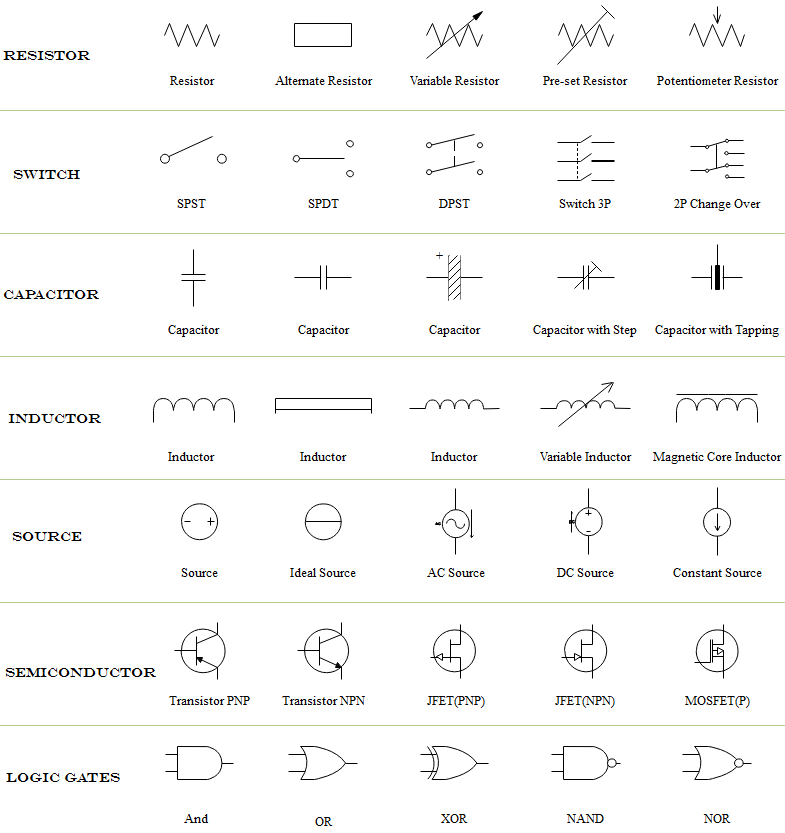
Once you know the language or terms of circuit diagrams, you are half way of being able to reading them. In circuit diagrams, there are many electrical symbols that are used to represent different electrical components and devices. Here is an overview of the most used symbols in circuit diagrams.

- Resistor: A resistor is used to restrict the amount of current flow through a device. It is usually represented by "R".
- Switch: There are several types of switches. SPST (Singe Pole Single Throw) allows the flow of current only when the switch is on. SPDT (Single Pole Double Throw) can lead the current of flow into two directions. DPST (Double Pole Single Throw) is used to isolate between the live and neutral connections in the main electrical line. These are the mostly commonly used ones.
- Capacitor Capacitor is a device that is used to store electrical energy. It is represented by letter "C".
- Inductor: Inductor is used to produce a magnetic field when a certain current is passed through the wire.It is represented by letter "L".
- Source: It could be a battery or anything that provides electricity.
- Logic Gates: There are several different types of logic gates. "AND" gate, "NAND" gate, "OR" gate, "NOR" gate, "EX-OR" gate, "EX-NOR" gate, "NOT" gate, etc.
Once you know the language and symbols of electrical drawings, you will be able to read circuit diagram. To be able to read circuit diagrams, it’s important to keep the basic knowledge of the field in mind. The more you get to know the languages and drawing symbols of electrical designs, the more prepared you will be while reading circuit diagrams.
Download this awesome schematic diagram maker and view built-in schematic diagram examples:


