Process Flow Diagram Symbols and Their Usage
Do You Want to Create Your Process Flow Diagram?
EdrawMax specializes in diagramming and visualizing. This article explains everything you need to know to create your process flow diagram easily. Try it free now!
Process flow diagrams use special shapes to represent different types of equipment, valves, instruments, and piping flow. This article provides plenty of process flow diagram symbols and helps you understand and create process flow diagrams easily and quickly.
EdrawMax includes standard symbols depicting mechanical equipment, piping, piping components, valves, equipment drivers, instrumentation, and controls. These PFD symbols are assembled on the drawing in a manner that clearly defines the process flow diagrams. With the pre-made PFD symbols in EdrawMax, you can make a process flow diagram in minutes!
Contents
- What is a Process Flow Diagram?
- Process Flow Diagram Symbols - Equipment
- Process Flow Diagram Symbols - Valves
- Process Flow Diagram Symbols - Piping Lines
- Process Flow Diagram Symbols - Instruments
- Process Flow Diagram Symbols - Centrifuges
- Process Flow Diagram Symbols - Heat Exchangers
- Process Flow Diagram Symbols - Crushers
- Use EdrawMax for Process Flow Diagram Creation
What is a Process Flow Diagram?
The Process Flow Diagram is a graphical representation used to demonstrate significant components of a process in an Industrial plant or manufacturer; it is widely used in Chemical/petroleum or process engineering.
The Process flow diagrams are used to understand the process and its sequence, model a process, document it, ensure quality control and standards, and increase efficiency. It maps out the whole process from scratch to show how equipment and chemicals work in the plant. It is a visual way of stating a process; it includes tasks and steps in their sequence.
What's Included in a Process Flow Diagram?
A process flow diagram includes:
- Equipment
- Valves
- Piping Lines
- Instruments
- Centrifuges
- Heat Exchange
- Crushers
And there is a detailed introduction to these symbols below; you can learn them with symbols and images.

An all-in-one platform for 210+ diagrams.
・ Simple alternative to Visio
・ 26k+ symbols
・ 10K+ free templates
・ 10+ AI diagram generators


Process Flow Diagram Symbols - Equipment
Pumps and tanks come in a variety of designs and shapes.
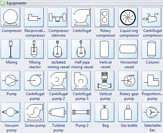
A compressor is a mechanical device that takes in a medium and compresses it to a smaller volume. A mechanical or electrical drive is typically connected to a pump that compresses the medium.
A pump is a mechanical apparatus that uses suction or pressure to raise or move liquids, compress gases, or force air into inflatable objects such as tires. Pump symbols may closely resemble those for compressors.
Mixing is a gear that combines some materials or combines them to form one substance or mass.
A mixing vessel is a container that is used to blend several components.
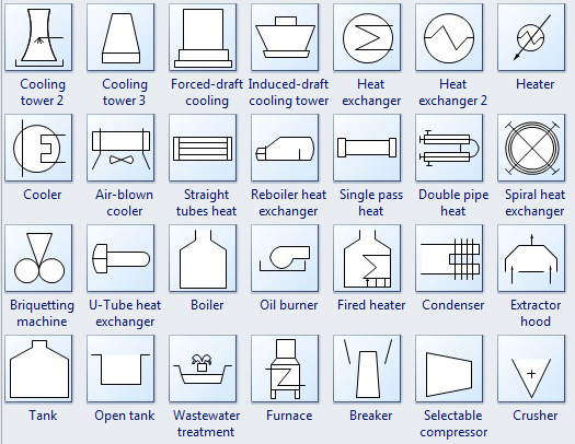
The heat exchanger is used to transfer heat energy between two process flows. Heat exchangers transfer heat energy through conductive and convective heat transfer.
Cooling towers transfer heat energy to the outside air through evaporation.
The cooler is a device, container, or room that cools air through the evaporation of water or keeps it cool.
A furnace is a tool for heating a continuous current of air through a fire within the apparatus without mingling the fresh air with combustion products.
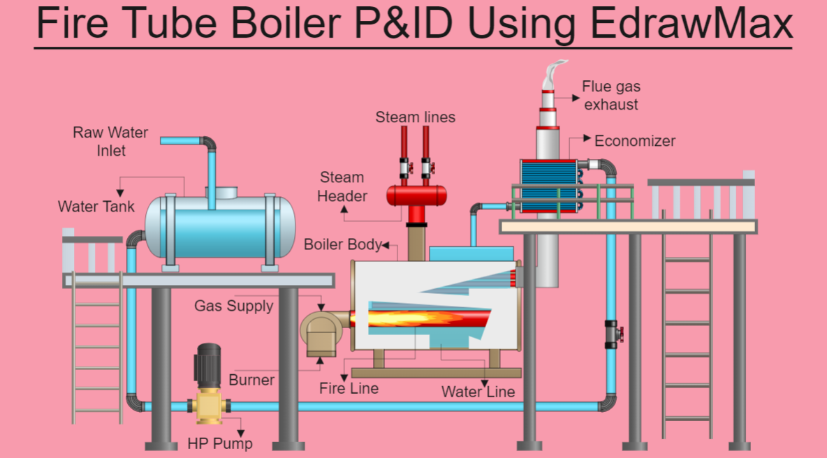
The boiler is a closed vessel where water or other fluid is heated.
The tank stores process fluids of various types under different process conditions.
Part 3: Process Flow Diagram Symbols - Valves
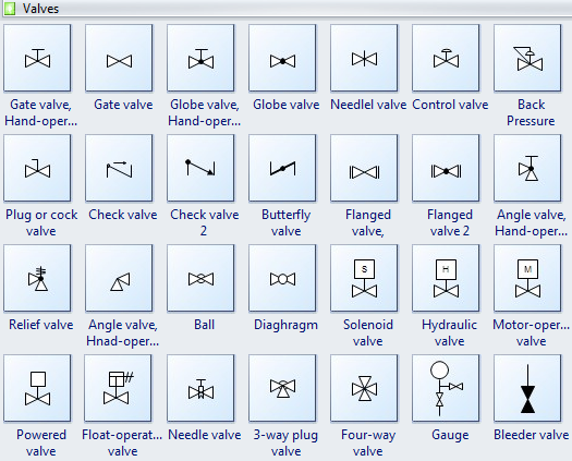
A gate valve is a device used to control the flow of liquids and gases.
A check valve, also known as a one-way valve, prevents the line of medium back.
A Globe valve is a mechanism to control or stop liquid or gas flow through a pipe.
A ball valve has a spherical disc, the part of the valve that controls the flow through it.
A butterfly valve is installed between two flanges using a separate set of bolts for each flange.
An angle valve is oriented at a 90-degree angle of the gate valve.
A needle valve has a slender, tapered point at the end of the valve stem that is lowered through the seat to restrict or block flow.
A control valve is used to control conditions such as flow, pressure, temperature, liquid level, etc.
A relief valve (RV) controls or limits the pressure in a system or vessel.
A bleeder valve releases air or gas through a valve opening to reduce the built-up pressure inside a tank or remove excess air or gas in a system.
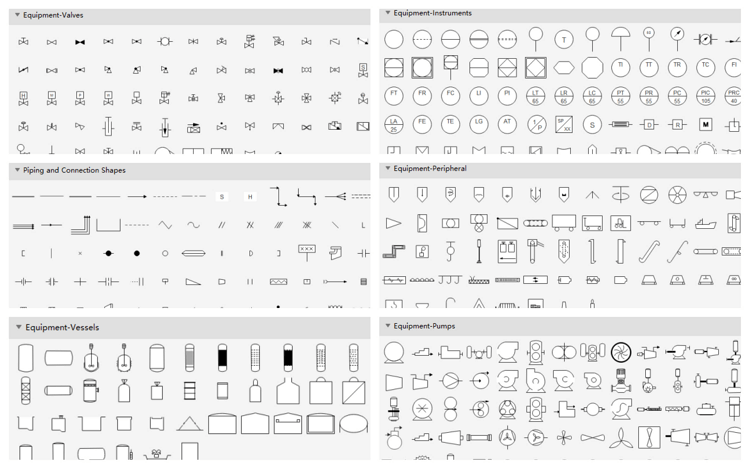
Part 4: Process Flow Diagram Symbols - Piping Lines
Process flow diagrams use memorable piping lines to represent signals transmitted between equipment. These symbols identify how the instruments in the process connect and what type of signal is being used (electrical, pneumatic, data, etc.).
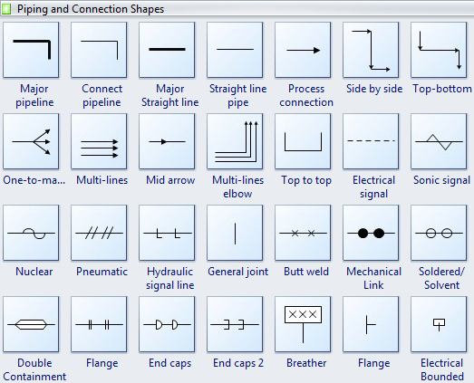
All lines are acceptable for process piping lines.
A significant pipeline is used to connect the equipment in any position.
A central straight line was issued to connect the equipment in the same horizontal or vertical position.
A process connection helps to create the process flow between equipment. Double-click the process connection to edit the description.
A flange is a projecting flat rim, collar, or rib on an object that serves to strengthen or attach it or (on a wheel) maintain its position on a rail.
A reducer is a component in a pipeline that reduces the pipe size from a larger to a smaller bore (inner diameter).
Part 5: Process Flow Diagram Symbols - Instruments
Process Flow Diagram uses symbols and circles to represent each instrument and how they are interconnected.
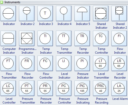
An indicator is a thing that indicates the state or level of something.
A thermometer is an instrument for measuring and indicating temperature.
A flow transmitter is a device used to measure the flow of a specific substance, usually liquid, through a series of pipelines or tubing.
A pressure transmitter is typically used to measure the pressure of gases or liquids.
As its name implies, a pressure recorder records the pressure.
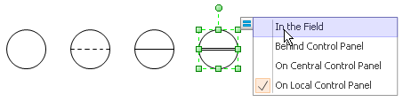
Users can easily change types of instrumentation symbols by clicking the quick action button while designing.
Part 6: Process Flow Diagram Symbols - Centrifuges
A centrifuge is a device whose function is to extract insoluble particles from a solution through spinning based on multiple factors, including size, density, viscosity, shape of the medium, and rotor speed.
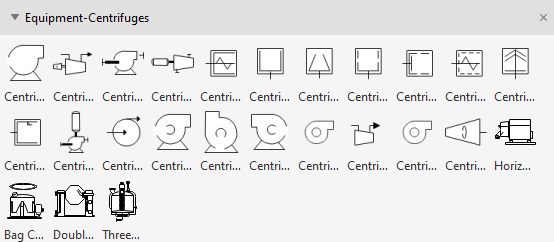
TYPES:
- Benchtop centrifuge
- Continuous flow centrifuge
- Refrigerated centrifuges
- Hematocrit centrifuge
- High-speed centrifuge
- Low-speed centrifuge
- Gas centrifuge
- Microcentrifuge
Part 7: Process Flow Diagram Symbols - Heat Exchangers
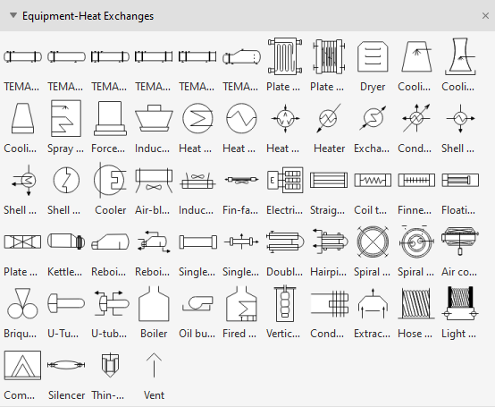
Heat exchangers are devices that transfer thermal energy from one fluid or gas to another when the two fluids are physically separated or blocked by a wall. It can be used for both heating and cooling purposes. This device's primary use or purpose is transferring heat from one medium to another and is also used for cooling.
TYPES:
- Shell and tube heat exchangers.
- Double pipe heat exchangers.
- Condensers, evaporators, and boilers.
- Plate heat exchangers.
Part 8: Process Flow Diagram Symbols - Crushers
Crushers are machines that reduce the size of heavy rocks, stones, and ores into a desired shape and form. They are widely used in aggregate production, construction, recycling, and mining. Crushers are used in industrial processes where machines use a metal surface to break, compress, or deform materials into small fractional shapes or denser masses.
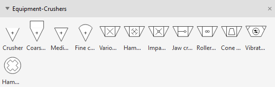
TYPES:
- Jaw crushers
- Gyratory crushers
- Cone crushers
- Compound crusher
- Crusher buckets
- Jaw crushers
- Mineral sizers
- Vertical shaft impactors
Part 9: Use EdrawMax for Easy Process Flow Diagram Creation
EdrawMax provides an extensive range of symbol libraries. These libraries are compatible with most mechanical and industrial requirements in piping, instrumentation, and all the required processes.
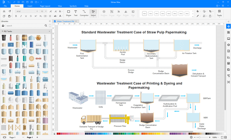
A Process flow diagram consists of basic symbols representing various functions, steps, or phases. It shows the sequence and interconnection of functions with lines and arrows between steps. It helps project stakeholders and members identify the different stages of a process and understand their connections.
EdrawMax is Pro industrial, chemical, production or business process documentation software for making process flow diagrams, workflow diagrams, general flowcharts and technical charts by providing thousands of worthy templates. The flowchart or the diagram created in EdrawMax consists of graphical keys and notations including symbols, interface points, labels, callouts and textboxes to describe every phase and step of the process.
Related Articles


