Comparison between PFD and P&ID
Difference between PFD and P&ID
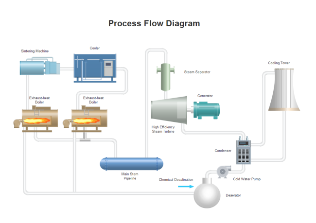
The process flow diagram (PFD) is used in chemical and process engineering. This kind of diagram shows the flow of chemical materials and the equipment involved in the process. In other words, a process flow diagram will tell us the relationships between the major components in the system. Generally, a PFD only contains the major equipment with no more details. And it also won't depict minor components, piping systems, piping ratings, and designations.
A PFD should include:
- Process Piping
- Major equipment symbols, names and identification numbers
- Control, valves and valves that affect operation of the system
- Interconnection with other systems
- Major bypass and recirculation lines
- System ratings and operational values as minimum, normal and maximum flow, temperature and pressure
- Composition of fluids
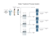
Here is a simple process flow diagram example.
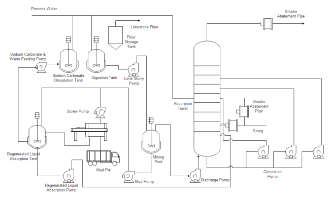
A Piping and Instrumentation Diagram (P&ID) includes more details than a PFD. It consists of both major and minor flows, control loops, and instrumentation. P&ID is sometimes referred to as a Piping and Instrumentation Drawing. P&IDs are mostly used by process technicians and engineering personnel.
A P&ID should include:
- Instrumentation and designations
- Mechanical equipment with names and numbers
- All valves and their identifications
- Process piping, sizes and identification
- Miscellaneous - vents, drains, special fittings, sampling lines, reducers, increasers and swagers
- Permanent start-up and flush lines
- Flow directions
- Interconnections references
- Control inputs and outputs, interlocks Interfaces for class changes Seismic category
- Quality level
- Annunciation inputs
- Computer control system input
- Vendor and contractor interfaces
- Identification of components and subsystems delivered by others
- Intended physical sequence of the equipment
A P&ID should not include:
- Equipment rating or capacity
- Instrument root valves
- Control relays
- Manual switches and indicating lights
- Primary instrument tubing and valves
- Pressure temperature and flow data
- Elbows and similar standard fittings
- Extensive explanatory notes
Common Points between PFD and P&ID
In both kinds of diagrams, arrows indicate the flow of material and symbols represent pumps, tanks, valves, and other equipment. The symbols used vary somewhat from organization to organization. So you may see several different symbols that all represent a motor. It is advisable to use a standard set of symbols like those provided by Edraw. Check out the vector PFD symbols and P&ID symbols.
EdrawMax
All-in-One Diagram Software
- Superior file compatibility: Import and export drawings to various file formats, such as Visio
- Cross-platform supported (Windows, Mac, Linux, Web)
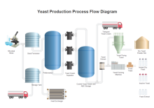
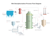
More PFD and P&ID Examples
The examples below can be downloaded and edited. It is often easier to modify an existing template than to start from scratch. To gain some more templates, download the free trial version of Edraw. Once it is installed, you can open the built-in samples directly in Edraw. You can easily zoom in, edit, and print the sample diagram.
|
|
|

|
Read More:

