Network Layout Tool
Network Layout
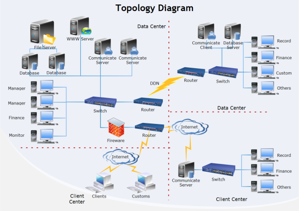
The placement of servers concerning the firewall and various other computers can affect both network performance and security. There may even be areas of the network that are more secure than others. Some of these areas may be further protected with an additional firewall. This following example illustrates how you can modify the default layout of the network.

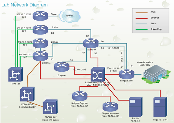
This diagram is a helpful troubleshooting tool for the IT employees when there is a problem in seeing a device on the network, adding items to the network, understanding what IP addresses are available, and sharing devices across the network. The logical diagram will include all of the information about the network's switches, IP addresses, etc.
Physical Network Layout
Network topology is the study of the arrangement or mapping of the elements (links, nodes, etc.) of a network, especially the physical (real) and logical (virtual) interconnections between nodes. The physical network layout is created by the administrator to represent the physical layout of the network. The diagrams are the most vital documentation needed to capture a wide variety of information in your network. Each computer is connected to the hub, and a cable line represents how it is connected. It will help you to visualize how much equipment you will need and show contractors or consultants what your idea for the network is.

Logical Network Layout
The logical network layout will be used to represent how your network connections are using the upper layer of the OSI and will help to understand your IP address. For example, if a workstation is no longer able to access the network, the administrator will be able to check their line, check the hub and verify the connection easily and rule out these possible errors more efficiently. It is the first step to be taken before setting up your network and needed to understand and maintain the different devices. After you have created your physical network diagram, the next step would be to create a logical network diagram. It is not a diagram that will be understood easily by management but is still a vital document for any company that has a network.
What is the best way to help others follow your networks? Connections will be the physical network diagram. And its connectivity, areas that are not covered in the physical diagram. With this diagram, the IT person will have a valuable reference guide for troubleshooting, training new employees, and aid outside vendors that may need to understand your network. This diagram will illustrate each node on the network and represents physically how the network fits together.

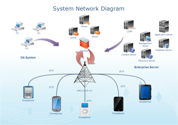
System Network Diagram Examples
A system network diagram template is ready-made in vector format for your own designs. You can find more network diagram examples.


