Layout of P&ID
In terms of layout, a P&ID should follow the criteria below.
1. Reading order: Criteria contained herein apply to reading a P&ID from the bottom or right side of the drawing.
2. Drawing size: standard size is 22" x 34" (560 mm x 864 mm).
3. Present each P&ID to avoid disorder and allow future modifications. Show no more than three pieces of major equipment per P&ID. Leave more space for text entry and easier reading.
4. Show primary flow on each P&ID from left to right. Show flow through equipment relative to actual arrangement (e.g., cooling water supply in bottom of exchanger tube bundle and cooling water return out top).
5. Line weight variety: Make primary process lines heavier than secondary and utility lines to show hierarchy. Change line weight with Line tool in Home tab.
6. Show off-page connector arrows for primary, secondary and instrumentation lines entering the P&ID horizontally 0.25" (6.4 mm) from the left inside borderline and exiting 0.25"(6.4 mm) horizontally from the right inside borderline. Utility connectors may be shown at any convenient location within diagram area.
7. Show the center point of a PSE (Pressure Safety Element) identification bubble 0.5" (12.7 mm) above a horizontal line or left of a vertical line and 0.5" (12.7 mm) away from the rupture disc or equipment.
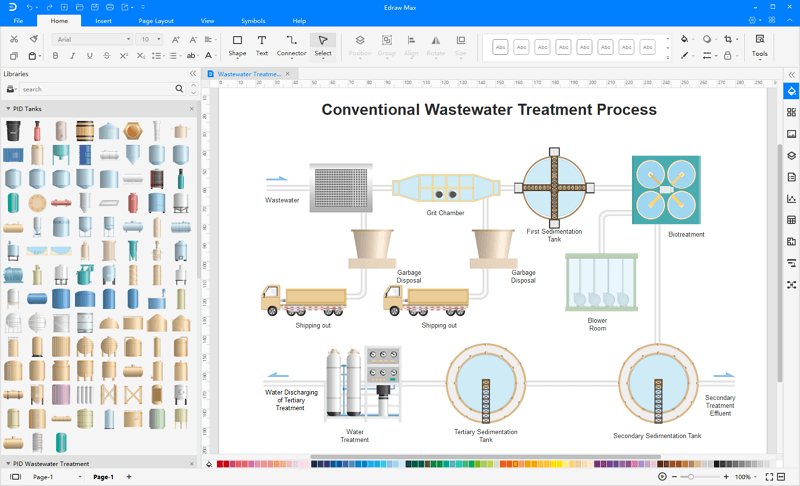
Here is a complete example of piping and instrumentation diagram created by Edraw.

More Related
How to Create Process Flow Diagram


