HVAC Plan Complete Guide
Edraw Content Team
Do You Want to Make Your HVAC Plan?
EdrawMax specializes in diagramming and visualizing. Learn from this HVAC plan complete guide to know everything about HVAC plan. Just try it free now!
Heating, Ventilation, and Air Conditioning System, more commonly known as HVAC, is a combination of multiple systems used to move air between indoor and outdoor areas. As you will learn here in this HVAC Plan today, HVAC systems are also used for heating and cooling private and commercial buildings. As Tony Fadell said,
"Thermostats are made by very large companies with no incentive to innovate. Their customers are contractors or HVAC wholesalers, not consumers. So why spend to make them better? It's a good business."
Over the years, several special technicians and engineers have started using an HVAC Floor Plan, which they discuss with the building's architect to ensure that all the equipment is performing in the right way. In this elaborated guide of the HVAC Plan, we will walk you through the different usages and benefits, how to read an HVAC Plan, and how easily you can create one using EdrawMax. After completing this HVAC Layout plan guide, you will easily be able to create, set up, and maintain your own building's HVAC systems. However, it is always recommended that you install and maintain high-voltage equipment under the guidance of an expert.
1. What is an HVAC Plan
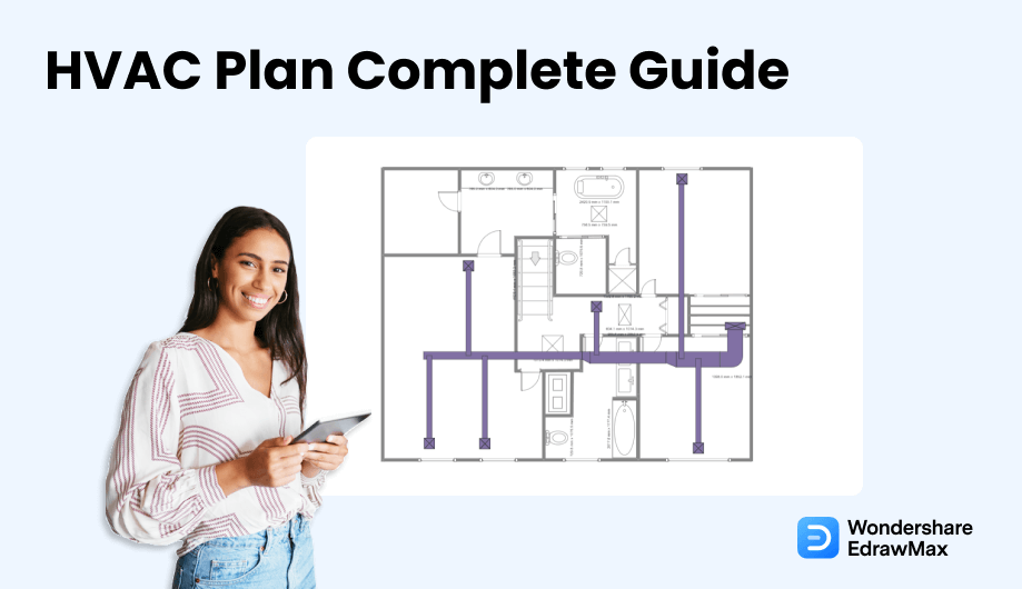
Several decisions are made during building a new building or when a commercial complex goes under renovation. One of the most important decisions is about the installation of HVAC systems. Like any other floor plan or architectural plan, an HVAC Plan refers to the 2D or 3D representation of all the materials or equipment needed by a special engineer to create, set up, and maintain the heating and cooling system of any other building.
It should be noted here that an HVAC Plan is a very important part of building construction or renovation. By including the HVAC layout in your architectural setup, you are ensuring that you have properly marked all the systems, they are easy to maintain by an outside engineer, and the systems will provide comfortably humid air while improving air quality by bringing in the fresh air.
An HVAC plan refers to the 2D or 3D representation of all the materials or equipment needed by a special engineer to create, set up, and maintain the heating and cooling system of any other building.
2. The Usages of HVAC Plan
As we learned here, HVAC systems provide the overall floor plan related to heating, cooling, and ventilation; they can be used in multiple ways depending upon the building and the availability of resources. Some of the important usages of having an HVAC Plan are:
- Easy Maintenance: Creating an HVAC Floor Plan while you build or renovate the building ensures that you will not waste a ton of money in maintenance. Since every setup, every cable description, every machinery is properly marked, the system maintenance engineer will easily rectify any persisting issue.
- Helps setting up the system: HVAC plans act as the first step in setting up the air conditioning and the thermal system of any personal or commercial building. The HVAC Plan becomes the point of reference for every purchasing, setting, and maintaining of the system.
- Elucidate the cost: HVAC Layout Plans helps in explaining how much money one will spend in procuring the equipment. Since minute detail is mentioned in the HVAC plan, the owner or the client will clearly understand how much money they are going to spend on it.
3. The Purposes of HVAC Plan
In simple words, the core purpose of an HVAC system is to maintain good indoor air quality through adequate ventilation with filtration and, at the same time, provide good thermal comfort. So, the core purpose of an HVAC plan would be to ensure that the entire HVAC system is properly configured in the private or the commercial compound.
There are several purposes of having an HVAC Plan, but here we have mentioned a couple of most important points to give you an idea of why you should always have an HVAC Layout Plan in place when you need to set up the heating, ventilation, and air conditioning systems.
- The purpose of having an HVAC plan is more than to help set up the HVAC system. It guides the builder and the architect about improving the indoor air quality and providing comfort for everyone who is currently inside the building.
- In case of any emergency, the system engineer will look at the HVAC Layout plans to understand which areas need immediate attention.
- Since every minute detail of the machinery, cables, and other power units are laid out on the plan, it makes it pretty easy for the engineers to install everything.
- Just by creating the HVAC plan, you ensure that you utilize all the available space in the building.
In simple words, the core purpose of an HVAC system is to maintain good indoor air quality through adequate ventilation with filtration and, at the same time, provide good thermal comfort.
4. The Symbols of HVAC Plan
It should be noted here that the HVAC layouts always come with several important symbols, just like any other floor plan. These symbols ease your efforts in making the correct HVAC plans and ensure that your HVAC layout floor plan is technically correct.
There are hundreds of HVAC symbols that you can incorporate into your design. In this HVAC floor plan guide, we have categorized the symbols into four categories to ensure that you understand them in the best possible way:
- HVAC Controls
- HVAC Equipment
- HVAC Ductwork
- HVAC Controls Equipment
Temperature: Temperature symbol refers to the temperature transfers to remove heat from indoor spaces and release it outside.
Humidity: Humidity affects air conditioning negatively because it cancels out the cooling effect.
Connector Line: Helps in connecting two different HVAC units.
Actuator: An actuator symbol represents a device that produces a motion by converting energy and signals going into the system.
Pump: A pump symbol starts with the standard circle and a directional arrow pointing out one end from within that circle.
Rotary Pump: Rotary pump symbol is a valveless pump symbol where vanes positively push the fluid on parallel revolving shafts.
Centrifugal Pump: Centrifugal Pump symbol is a "backward C" drawn in the middle, but sometimes it is omitted or drawn as a circle.
Reciprocating Pump: A reciprocating pump symbol is a graphical depiction of a device that uses a backward and forward movement to move fluid.
Straight Duct : With a straight duct of constant cross-sectional area, the velocity pressure remains constant along the length of the duct.
Miter Bend : A Miter Bend or Elbow symbol is a graphical illustration of a joint made by beveling each of two pieces to be joined, usually at a 45-degree angle.
Branch Duct : A branch duct symbol represents an air duct that branches from the main duct.
Y-Junction : Y-junction is a symbol added in those places where you need to combine two things into one. It can also be used in adding multiple pipes into one unit.
VAV Box : Variable Air Volume (VAV) is a heating, ventilating, and air-conditioning (HVAC) system.
Vane Axial Fan : Vaneaxial fan symbols are the graphical representation of essentially a tube axial fan with air guide vanes located either before or after the impeller.
Air Flow Station : The air measuring station (AMS) symbol provides accurate airflow measurement.
Filter : In HVAC systems, filters are used in those areas where you need to filter out the outside air.
All the office layout symbols discussed here in this article are readily available in EdrawMax or EdrawMax Online.
- HVAC Controls
- HVAC Equipment
- HVAC Ductwork
- HVAC Controls Equipment
5. Preparations Before Starting HVAC Plan
If you are a student who is learning about HVAC systems or an expert who has designed multiple HVAC systems in the past, there are certain things that you should always follow when you start working on an HVAC layout plan. We have highlighted some of the important steps, but you can modify these steps as per your expertise in this area.
- Analyze the site
- Discussion with an Architect
- Energy Efficiency
- Design for Maintenance
- Be Practical with Approach
Even before you sit down and start designing the HVAC plan for the building, you should either see the blueprint or the site plan or go and visit the site to understand what kind of HVAC systems you can set up at the provided cost. Once the site is analyzed, you can sit down to start creating the HVAC Floor Plan.
If you are a technical expert assigned to set up the HVAC system in a building, you should first sit down and discuss the layout plan with the architect. An architect will be the right person to inform you what kind of ventilation and heating devices you can install in the building. Once you have all the data, you can create the HVAC plan design.
One of the greatest advantages of having an HVAC system in the building is improving the operating efficiency of all the equipment. When designing the HVAC Plan, try to look for such devices that offer capabilities and efficiencies that were not available two or three decades ago. For instance, you can add the Variable Refrigerant Flow (VRF) in the HVAC Floor Plan. As per the reports, in a VRF system, the compressor's speed differs as the cooling load on the system changes. This process results in saving energy in the long run.
One of the biggest complaints by the technicals is that the design engineer did not provide a way to maintain the HVAC system. So, when you design the HVAC Floor Plan, ensure that you keep the maintenance part in your mind. For instance, suppose you have installed a centralized air-conditioner in a building. However, when you designed the layout, you did not include the ways to replace the air vents. When the maintenance engineers are asked to replace the air units, they will have a tough time finding a way. In most scenarios, they will have to demolish the wall and replace the entire unit. In order to avoid such issues, you should always think about maintenance when you design the HVAC plans for the building.
When creating the HVAC Plan, always discuss the requirements and the budget from the building owner or your client. Remember to be realistic when it comes to adding or modifying certain units. Do let the person in charge know about the equipment you have added to the HVAC Floor Plan and what purpose they serve. A well-documented HVAC Plan will help you in conveying your messages effectively.
Only have a detailed preparation can people to have a good base of HVAC design. Once have prepared the HVAC design and some other elements, you may move into next step.
- Consider the blueprint, or what kind of HVAC systems;
- Consider the layout plan with the architect;
- Consider the design for maintenance ;
- Consider the HVAC plan to be realistic.
6. How to Design a HVAC Plan in General
There are two ways of designing the HVAC plan for any building. One is an old way to examine the site and lay out everything on the paper physically. Another one is where you use floor plan makers , like EdrawMax, to do the job for you! Before we provide you with the guide to creating the HVAC plan using EdrawMax, let us show you the general HVAC plan method.
Step 1: Understand your design goal
Before you start designing the HVAC plan, you should understand that your design should serve a vital purpose. In simple words, your HVAC plan serves as the guide for the rest of the creation purpose, where you mainly focus on efficiency and optimization. Discuss the design goal with your client, and after analyzing the site, you can proceed to the next step of designing the HVAC plan.
Step 2: Consider the HVAC Units
After finalizing the HVAC goal, you can start choosing the HVAC units that you need to add to the HVAC plan. Some major units are traditional, modern, and hybrid split systems. In most cases, we use the traditional HVAC system for residential properties. So, you need to have a clear understanding of the building.
Step 3: Consider the Building Layouts
It is always recommended to consider the building layout before designing the HVAC plan. Visit the place in person and then understand which HVAC units will go at which location. Please note it and even click some pictures for future references.
Step 4: Add HVAC units
Now that you have analyzed the area and finalized the HVAC units, you can draw them on paper. Ensure that you properly label your units to avoid confusion.
Step 5: Plan for Future Expansion
Always leave some room for future revisions. In your HVAC floor plan layout, make a table that will let you note your revisions. Since you are using a physical copy to create the HVAC plans, you must make multiple copies until you finalize your HVAC plan design.
Step 6: Consult an Expert
When you have created the HVAC plan, you should brief an HVAC expert about your planning. They can help address multiple issues that might arise when you start setting up the HVAC units in the building.
- Understand your design goal;
- Consider the HVAC units and the building layouts;
- Add HVAC units;
- Plan for future expansion;
- Consult an expert.
7. How to Design a HVAC Plan in EdrawMax
Now, as you have seen the complicated way of designing the HVAC plan, let us walk you through the easy way. With the help of EdrawMax, you can create an HVAC layout within minutes. Gone are when you had to make the symbols physically; now, you can easily access all the HVAC symbols right from the EdrawMax dashboard.
Following are the basic steps that you need to follow to create the HVAC plan for your building. It should be noted here that some of the steps may change or upgrade depending upon your requirement, but the zest of designing the HVAC plan will remain the same.
Step1 Open EdrawMax and Login
If you are using the offline version of EdrawMax, then open the tool in your system. If you wish to have remote collaboration, head to https://www.edrawmax.com/online/ and log in using your registered email address. If this is your first time using the tool, you can register yourself using your personal or professional email address.
Step2 Template Selection
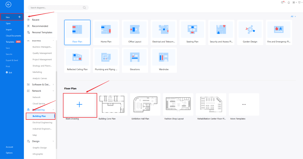
If you need to access the free HVAC templates, click on the 'Templates' option from the left panel of the EdrawMax tool and type 'HVAC' in the search bar. You will see hundreds of free HVAC templates, like Factory HVAC, Building Zone HVAC, Centrifugal Fan HVAC Plan, and more. Click on any of these templates and start customizing as per your requirement.
Step3 Create from Scratch
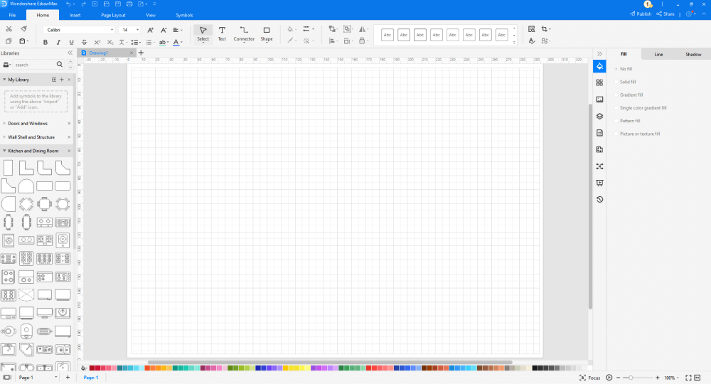
In order to create the HVAC plan from scratch, click on 'Building Plan,' which you can find on the left panel of the tool. Upon clicking, you will see a list of different 'Building Plans' that you can create with EdrawMax, like Floor Plan, Home Plan, Office Layout, and more. Click on 'Plumbing and Piping Plan' and select the free template or click on '+' to design the HVAC from scratch.
Source: EdrawMax
Step4 Select the Symbols
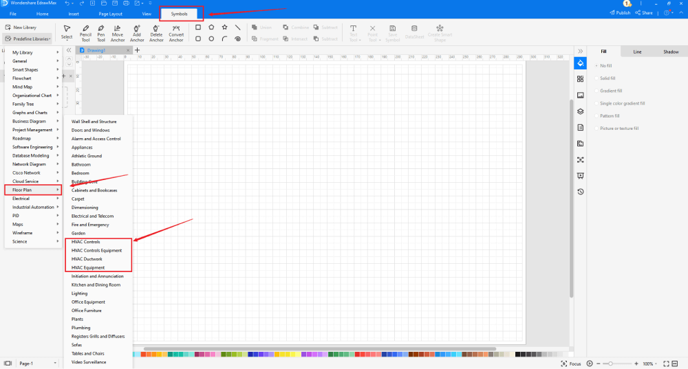
In order to use the HVAC symbols, you need to select the 'Symbols' tab from the toolbar. From there, click on Predefined Libraries > Floor Plan, and then select the HVAC symbols that you need. From the left side of the drawing screen, you will now easily access and insert these vector-enabled HVAC symbols.


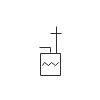

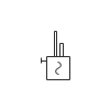

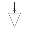
Know more about HVAC symbols, and try to drag and drop the symbols you want to customize your HVAC plans.
Step5 Add Components
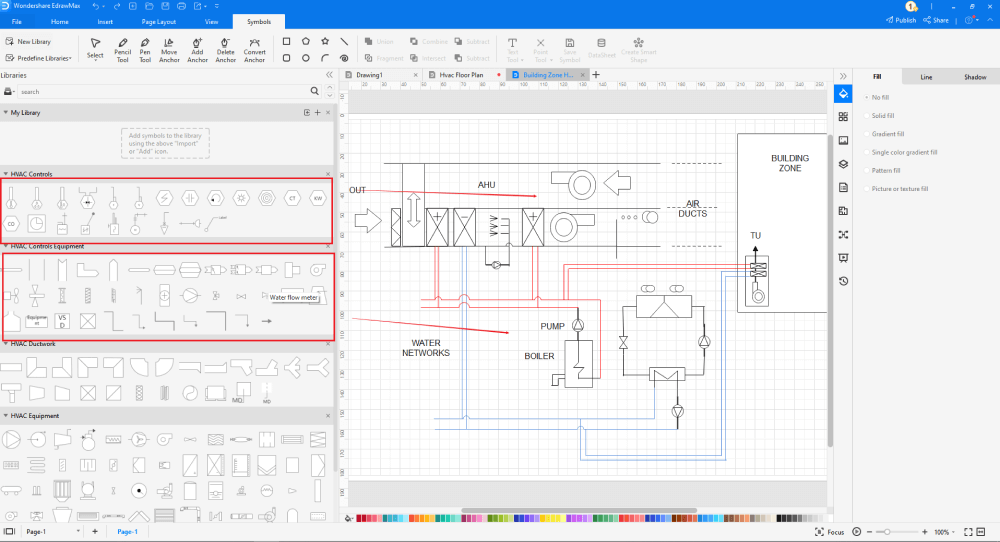
Now that you are on the drawing canvas, you can create the HVAC plan. Remember to add additional components and equipment you deem fit for the building.
Step6 Export or Share
Once your HVAC layout plan is ready, you can easily share it using EdrawMax's special sharing feature. This HVAC plan maker lets you export your file in multiple formats, like JPEG, PNG, PPTX, PDF, and more. In addition to this, you can easily share the HVAC floor plan via email or on different social media platforms, like Facebook, Pinterest, Line, and LinkedIn.
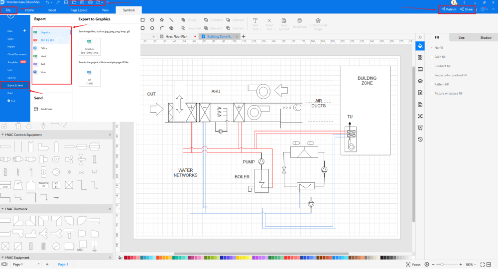
Basically, it is simple to create a HVAC plan in EdrawMax, just grab a template and keep customizing, drag and drop professinal HVAC symbols to make your plan better. If you are still confusing about how to make a HVAC plan in EdrawMax, just check this HVAC Plan guide, or check the video below. Or you can find more tutorial videos from our Youtube
8. How to Read an HVAC Plan
People find it difficult to read an HVAC Plan drawing in most cases. Here, we will help you understand how easy it is to read a mechanical HVAC blueprint. However, it would help if you also understood that HVAC plan drawings specify the location and installation details of the heating, cooling, and ventilation systems. Since the HVAC system varies from building to building, the number of equipment and efforts also differ. However, there is a systematic way to read an HVAC plan. In order to understand the HVAC Plan drawing, we have categorized the layout in five points:
Title Block & Symbols
A well-designed title block will help you communicate with your architect or system's engineer. At the same time, title blocks and symbols (legends and labels) will help your maintenance engineers. Title Blocks contains a few important segments:
- Legends & Notes: HVAC Symbols and Legends are always included in the HVAC Plan to help the readers understand the drawing. Always add the right symbols notations at the right side of the HVAC Floor Plan.
- Revision Table: It is always advisable to add a revision table at the bottom of the HVAC Plan. A simple revision table will help the team track the past changes made in the HVAC plan drawing.
- File Name: Many engineers forget to give the HVAC Plan the correct name properly. This mishap results in confusion at the later stages. So, when you start designing the HVAC plan, remember to properly give the project's name at the top of the floor plan layout.
Ventilation System Drawing
All the HVAC systems include the HVAC ventilation drawings. From slab & wall openings to grilles & dampers, a ventilation drawing plays a vital role in designing the HVAC system. There are several other important elements to the ventilation system drawing that you should know in order to read the HVAC Floor Plan design, like:
- Equipment Tag: A good HVAC Floor Plan will always include equipment tags and other specifications of the ventilation fan. The equipment tag includes the system, its location, fan number, and more in most cases.
- Specifications: All the machines have a specific specification written on them. Try to incorporate those specifications in the HVAC plans as well.
- Brand & Model: Brand and model are straightforward information about the products you have installed. Please read them and understand what process they serve.
Air Conditioning System Drawing
In the HVAC plans, you will find several symbols and acronyms used in the air conditioning system drawing.
- Equipment Tag: As the ventilation system draws, air conditioning units also have their respective tags linked. In most HVAC Floor Plans, you will find the tag name, capacity, and airflow mentioned in them.
- Acronyms: Some of the most commonly used acronyms are: IDU (Indoor Unit), ODU (Outdoor Unit), AHU (Air Handling Unit), FCU (Fan Coil Unit), VRV (Variable Refrigerant Volume), VRF (Variable Refrigerant Flow), CHW (Chilled Water).
Control Panel Diagrams
HVAC Systems are filled with multiple electrical components used in different control panels. As you see from any HVAC Plan design, the HVAC control panel drawing is a single line diagram and the panel layout drawing.
- Single Line Diagram: In all the HVAC Floor Plan layouts, the single line diagram shows the cable size, the equipment load, and other important specifications on electrical components, like starters, earth cables, MCCBs, etc.
- Cable Size: In HVAC Plan, we always indicate the cable sizes in electrical single line diagrams. It should be noted here that cable sizes start with the quantity followed by the number of cores, the cross-sectional cable area, the cable type, and the cable trunking. For instance: 4*11D/12mm2 FR CABLE C/W E/WIRE ON CABLE CONDUIT will read as Four numbers of eleven-core twelve square millimeters fire-rated cable complete with earth wire on cable conduit.
Section & Elevation Drawings
Section and elevation drawings are different from the air conditioning drawings as they serve a whole different purpose.
- Section Drawings: In HVAC Plans, a section drawing starts by slicing through a particular area to represent the view of the section. Readers are then prompted to read a separate drawing to see the side view of that particular section from the HVAC Floor plan.
- Gridlines: While creating the HVAC Plans, it is always advisable to add the gridlines. Gridlines always help the reader to understand if you have cut through the building design or the entire plant room.
9. The HVAC Plan Examples & Templates
There are 3 examples of HVAC plans that you can refer or use immediately. Just click the image to download EdrawMax, and download the templates accordingly. Then double click to open the templates and customize as your prefer. Or open the templates from EdrawMax Online , and duplicate the templates. Click this HVAC plan examples to get more inspirations.
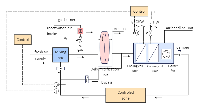
Example 1: HVAC System Diagram
In the following HVAC Layout plan, we have shown several important types of equipment of the HVAC system, like mixing box, dehumidification unit, controlled zone, cooling coil unit, air handling unit, gas burner, exhaust, damper, extract fan, and more. As we see from the following HVAC system diagram, such elaborative designs are the backbone of building the mechanical systems of any building. It should be noted here that HVAC systems can be central and local, depending on their zones, locations, and distributions. As shown here, local HVAC systems are located inside a conditioned zone and have no requirement for ductwork. At the same time, such local HVAC systems include local heating, local ventilation, local air-conditioning, and split systems.
Example 2: HVAC Plan Template
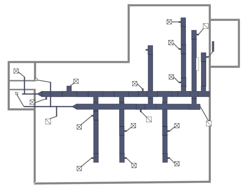
In the following HVAC plan template, we have illustrated an air return system that performs air suction, draws the air through a filter, and then passes it into the main control system. In addition to this, we have added filters and exhaust outlets in this HVAC plan template. These filters improve the indoor air and pass them through the exhaust outlets. It should be noted here that creating HVAC plans is very important when you start working on the floor plan of any building. Sometimes these HVAC layout plans look tedious, and in that case, you can start using EdrawMax to create technically correct HVAC plans using free templates.
Example 3: Building Zone HVAC Plan
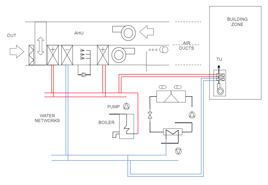
As shown in the following image, a building zone HVAC plan has three core areas, which are: Installation Qualification (IQ), Operational Qualification (OQ), and Performance Qualification (PQ). In the following HVAC Floor plan, we have added several important types of equipment, like water networks, boiler, pump, air ducts, and have also specified the building zone in detail. It should be noted here that while creating the HVAC layout plan for a building, the HVAC system plays an essential role in providing documented evidence about the accuracy of results that help in maintaining the overall system. You can create such HVAC plans using the free in-built templates by EdrawMax.
10. Free HVAC Plan Software
As you saw in the elaborated guide on the HVAC plans, you will have a hard time if you go ahead and create the HVAC layout using the old-age methods. In addition to this, not everyone can master the commands of high-tech tools that offer HVAC designs. If you are a beginner, just starting, or a professional who has created several HVAC layouts in the past, you will find that EdrawMax are among the most accessible tools in the market.
Unlike other tools with a stiff learning curve, EdrawMax is straightforward hvac drawing software. Just log in to the tool and start designing the HVAC plans using the free HVAC templates and symbols. In addition to this, several other features make EdrawMax a go-to tool for all of your drawing needs, like:
- EdrawMax Online offers seemingly effortless remote team collaboration, which allows you to get real-time inputs or feedback from your team members.
- EdrawMax has over 50,000 vector-enabled symbols that let you create HVAC and other floor plan diagrams for your personal and professional needs. These free HVAC symbols can be resized, reshaped, and recolored as per your need.
- With EdrawMax, you get access to thousands of templates that ease your efforts in creating any complex HVAC layouts.
- Unlike other tools where you can only create a handful of diagrams, EdrawMax lets you create over 280 different types of diagrams (way more than Microsoft Visio). Just by using EdrawMax, you can create an HVAC floor plan, building plan, office plan, seating charts, blueprints, site plan, and other 2D architectural plans for your needs.
- With EdrawMax, you can easily connect a boiler to a pipe in just a few easy steps. It makes it easy for a designer or a system engineer to lay out their ductwork and focus on the 'big picture.'
key Features of EdrawMax:
- EdrawMax comes with free HVAC Plan templates that are 100 percent customizable;
- The built-in vector symbols let you easily add components to your design;
- You can easily share the HVAC Plan design with your team and see the live revisions made by your team;
- EdrawMax lets you export the file in multiple formats, including MS Docs, PPTX, JPEG, PNG, PDF, and more;
- EdrawMax has a strong community of 25 million users who update the template community with their creative projects;
- EdrawMax is considered the best tool for beginners and professionals because of the user-friendly dashboard and easy drag-and-drop feature.
11. Final Thoughts
HVAC plans play a vital role in a building's overall design. It will not be wrong to say that HVAC plans are the backbone of any building's architecture as they provide the building's heating, ventilation, and air conditioning system. While creating the HVAC layout, remember that you are making it for the specialized engineers or the architects, so always label every part correctly. In most cases, these HVAC plans are printed and distributed offline while the engineers work on the building.
As you learned in this HVAC plan guide, EdrawMax not only helps you create an HVAC layout by using the free templates and symbols it also lets you share it with your team in real-time. In addition to this, EdrawMax also offers a direct print option from the panel. Here, you do not have to go and find a different tool just to print out. Just go to the Print option and print the high-quality HVAC layouts for your official needs. All in all, EdrawMax is a powerful tool, well-equipped to help you design the complex HVAC layout with utter ease.

Floor Plan Complete Guide
Check this complete guide to know everything about floor plan, like floor plan types, floor plan symbols, and how to make a floor plan.
You May Also Like
Landscape Plan Complete Guide
Knowledge
Table Plan Complete Guide
Knowledge
Seating Chart Complete Guide
Knowledge
Office Layout Complete Guide
Knowledge

