A Simple Guide for Creating a Use Case Diagram
Use case diagram allows you to model system functions, and present how actors interact with those functions. In this page, you will learn how to draw an excellent user case diagram with pre-made shapes and smart connecting.
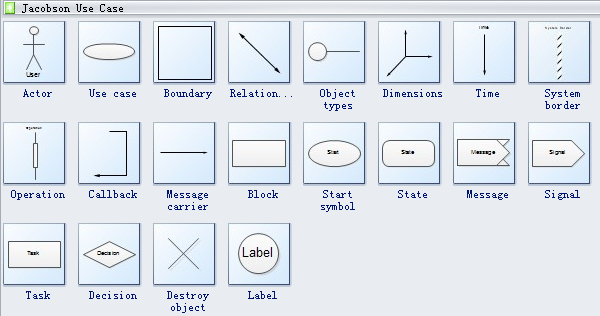
Built-in Use Case Symbols
Start a New Use Case Diagram Drawing Page
1. Start Edraw, on the File menu, point to New.
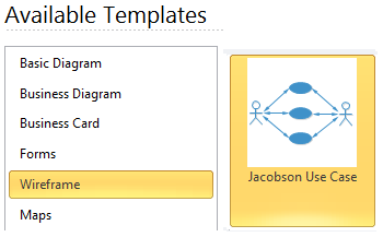
2. Click Software from the Template Category, and then double click Jacobson Use Case icon to start a new page.
3. On the left, a library for Jacobson Use Case Diagram is open. All the commonly used symbols are included.
Add a System
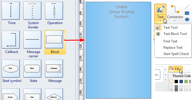
From the built-in Use Case Library, drag a block shape on the page to represent the system. Resize the block by dragging the control handles. You can fill it will a color, and name the system using Text tool.
Add Actors
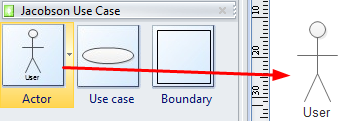
From the library, drag a built-in actor symbol, and drop on a suitable position of the canvas.
Add Use Case
From the library, drag a built-in use case symbol, and drop in the system block. To resize the use case shape, select it and drag the control handles. Double click on the shape to add text.

Connect Actor with Use Case
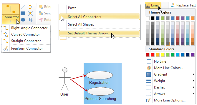
Draw a connector using Connector button under Home tab. To change connector style, you can right click the mouse and choose Select All Connectors, then click Line button to set line style. To set the line style ahead, you can right click the mouse, and choose Set Default Theme, Arrow...
Apply a Theme
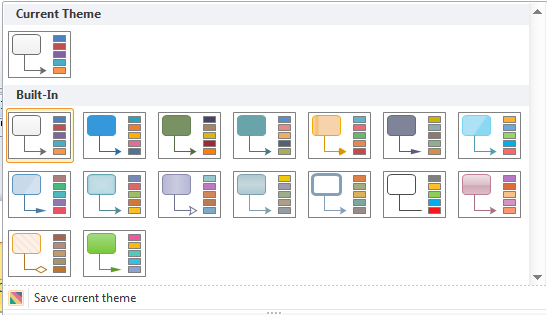
Under the Page Layout tab, a group of nice themes with advanced colors and effects is available for you to choose.
The Final Use Case Diagram
Download a free trial and see first-hand how quickly and easily you can create great-looking use case diagram.
Use Case Diagram Software for Linux
