Simple Electrical Circuits Introduction
As we all know that modern life is overwhelmingly dependent on electricity, it is quite important for people to understand simple electrical circuits. A simple electrical circuits introduction is a good assistant for you to better know electrical circuits.
You may try electrical drawing software, which has built-in standard electrical symbols to rapidly and correctly draw electrical circuits.
EdrawMax
All-in-One Diagram Software
- Superior file compatibility: Import and export drawings to various file formats, such as Visio
- Cross-platform supported (Windows, Mac, Linux, Web)


The Definition of Electrical Circuits
An electrical circuit is a closed loop of conductive material that allows electrons to flow through continuously without beginning or end. There is continuous electrical current goes from the supply to the load in an electrical circuit. People also say that a complete path, typically through conductors such as wires and through circuit elements, is called an electric circuit.
An electrical circuit is an electrical device that provides a path for electrical current to flow. After you get the definition of the electrical circuit, now we are going to show you three simple electrical circuits.
Switch Circuit
A switch is a device for making and breaking the connection in an electric circuit. We operate switches for lights, fans, electric hair drier and more many times a day, but we seldom try to see the connection made inside the switch circuit. The function of the switch is to connect or complete the circuit going to the load from the supply. It has moving contacts which are normally open.
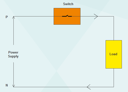
With a switch you can turn the device on or off, therefore, it is a very important component in an electrical circuit.
DC Lighting Circuit
As you can see from the picture below that the LED lamp uses DC supply battery. The battery is bipolar, one is anode and the other is cathode. Moreover, the anode is positive and the cathode is negative. Also, the lamp itself has two ends, one positive and the other is negative. Therefore, the anode of the battery is battery is connected to positive terminal of the lamp, meanwhile the cathode of the battery is connected to the negative terminal of the lamp.
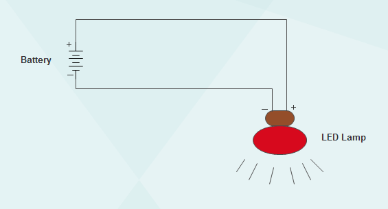
Once the above connection is complete, the LED lamp will light. Although it is simple electrical circuit, many people have no idea how to deal with the connection correctly.
Thermocouple Circuit
If you are looking to build a temperature-sensing device or you need to add sensing capabilities to a large system, you will have to familiarize yourself with thermocouples circuits and understand how to design them. A thermocouple is a device consisting of two dissimilar conductors that contact each other at one or more spots, and it is used to measure temperature. As you can see from the picture below that a thermocouple is made of two wires - iron and constantan, with a voltmeter. If the cold junction temperature is kept constant, then the EMF is proportional to the temperature of the hot junction.
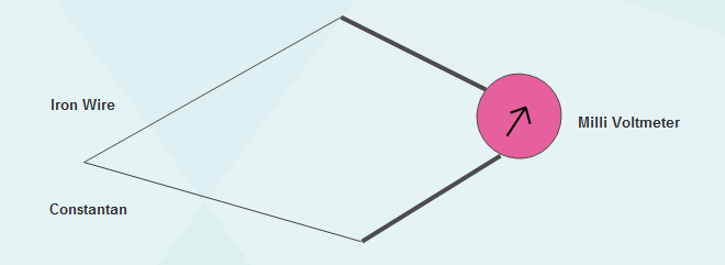
Voltmeter will measure the EMF generated and this can be calibrated to measure the temperature. The temperature difference between the hot and cold junction will produce an EMF proportional to it. Because thermocouple junctions produce such low voltages, it is imperative that wire connections be very clean and tight for accurate and reliable operation. Despite these seemingly restrictive requirements, thermocouples remain one of the most robust and popular methods of industrial temperature measurement in modern use.
More Related Articles
How to Read Electrical Circuit

