Learn Electrical Circuits from Four Examples
An electrical circuit is a closed connection of batteries , resistors , wires, switches, etc. An electrical circuit consists of voltage loops and current nodes. Many people are confused with complex electrical circuits, however, if they develop a solid understanding of the below four electrical circuit examples, it will be easier for them to read complex electrical circuits.
You may try electrical drawing software which has built-in standard electrical symbols to rapidly and correctly draw electrical circuits.
Electrical Circuits Examples - Energy Meter or Motor Meter
Motor meter is also called energy meter. Energy is the total power consumed over a period of time and it can be measured by a motor meter or energy meter. Moreover, energy meters are used in all power supply lines to every house in order to measure the power consumed in both DC and AC circuits. Energy meter is an instrument that measures the amount of electric energy used by a consumer. The meter is calibrated in kilowatt-hours. One kilowatt-hour is the amount of electric energy required to provide 1,000 watts of power for a period of one hour.
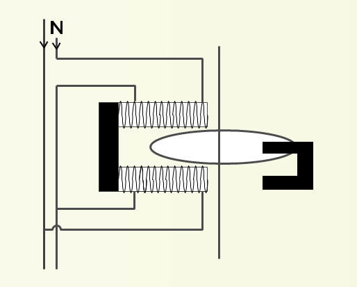
There is an aluminum disc which rotates continuously when power is consumed. Energy meters have a pressure coil and a current coil. When the voltage is applied across the pressure coil, current flows through the coil and produces a flux which exerts torque on the disc. The resultant torque acts on the disc and results in a rotation on the aluminum disc which is proportional to the energy utilized and which is recorded in the energy meter.
Electrical Circuits Examples - Multimeter Circuit
A multimeter is a black box of electronic circuitry that allows you to troubleshoot just about any type of electrical wiring or device. With all its numbers, dials and switches, a multimeter (also known as a volt-ohm meter, or VOM) can be pretty intimidating.
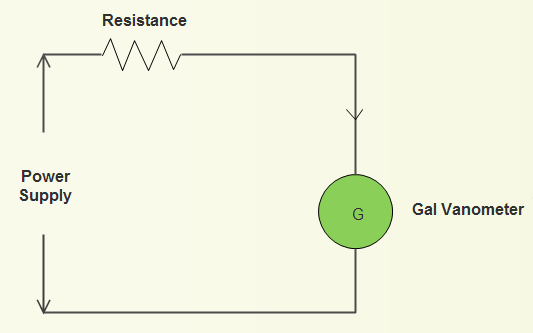
VOM can pay for itself quickly by simply analyzing whether the dozens of batteries devoured by toys and electronic devices are still good. VOM consists of a galvanometer connected in series with a resistance. The current flow in a circuit, that is, voltage across the circuit can be measured by connecting the terminals of the multimeter across the circuit. A multimeter is a handy tool that you use to measure electricity, just like you would use a ruler to measure distance, a stopwatch to measure time, or a scale to measure weight.
Electrical Circuits Examples - Current Transformer Circuit
The current transformer is a type of "instrument transformer" aiming to produce an alternating current in its secondary winding which is proportional to the current being measured in its primary. Current transformers can reduce or "step-down" current levels from thousands of amperes down to a standard output of a known ratio to either 5 Amps or 1 Amp for normal operation.
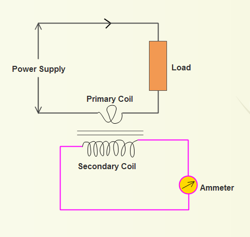
The secondary winding of the transformer is connected to an ammeter. The transformer will step down the current to a value that can be measured by the connected ammeter. Current transformers can perform circuit control, measure current for power measurement and control, and perform roles for safety protection and current limiting. They can also cause circuit events to occur when the monitored current reaches a specified level.
Electrical Circuits Examples - Single Phase Motor Circuit
Single-phase distribution is used when loads are mostly lighting and heating, with few large electric motors. Single-phase motors are designed to operate from a single phase supply and can perform a wide variety of useful services however, they need additional circuits for starting, and such motors are uncommon above 10 or 20 kW in rating. A single phase motor has two terminals in the terminal box of the outer casing. One of these terminals is connected with the live wire of the power circuit and the other is connected with the neutral wire.
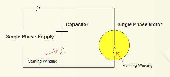
When the electrical supply goes to the motor, the motor will run until the power supply is cut. Even a fan works on this single phase motor. Sometimes the fan will not start when we switch it on. The reason is that the capacitor employed for making the single phase motor self starting is not functioning. The best way to solve this problem is to replace the capacitor.

