How to Create UML Deployment Diagram Easily
Part 1: What is The UML Deployment Diagram?
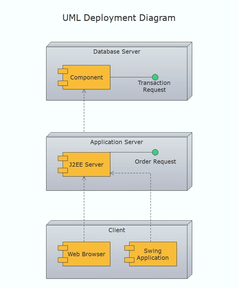
UML Deployment diagram is a structure diagram which shows shows architecture of the system and models the physical deployment of artifacts on nodes. And the purposes of it are describing the hardware components used to deploy software components, visualizing hardware topology of a system and describing runtion processing nodes. Just take describing a website as an example, a UML deployment would show what hardware components exist, what software components run on each node, and how the different pieces are connected.
Unified Modelling Language (UML) is a type of language used to illustrate the inner workings of a system, which include its actors, actions, roles, and classes. Originally used in the fields of software and engineering, UML has now made its way into business, and is a popular method of documenting business processes.
The Usage of UML Deployment Diagram
The major usage of UML deployment diagrams used by system engineers is to describe the physical components or hardware’s distribution and association. We can also visualize UML deployment diagrams as hardware components or nodes where software components reside. Following are usages to which UML deployment diagrams are applied.
- To model the hardware topology of a system.
- To model embedded system.
- To model hardware details for a client/server system and a distributed application.
- Forward and reverse engineering.
Part 2: How to Create A UML Deployment Diagram?
How to make a UML deployment diagram easily? Using EdrawMax to create your own UML deployment diagram in minutes. If you have had Edraw installed, you can create a more detailed UML deployment diagram by using the UML deployment diagram templates.
Step 1: Open EdrawMax desktop software or EdrawMax web-based application.
Step 2: Navigate to [New] > [Software] > [UML Modeling] in EdrawMax.
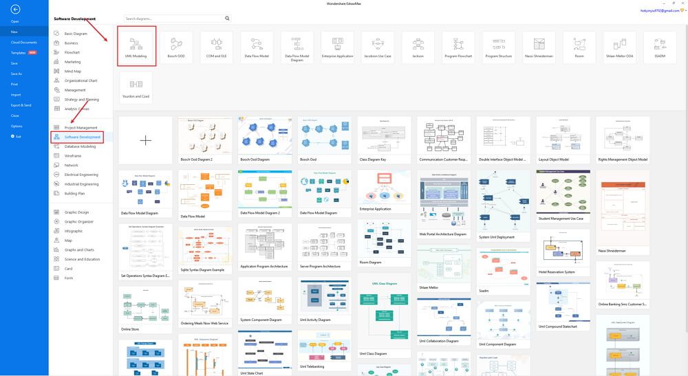
Step 3: Select one UML deployment diagram template to edit on it or click the [+] sign to start from scratch. Also, you can use massive UML deployment diagram symbols and elements from libraries in left menu to customize your UML deployment diagram.
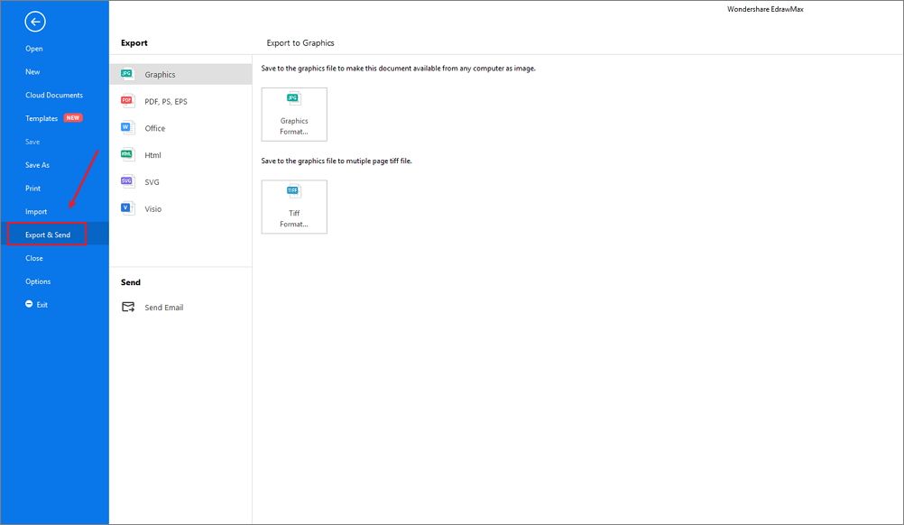
Step 4: Once finished your creation, you can export the file in multiple formats, including Graphics, PDF, editable MS Office file, SVG and Visio vsdx file.
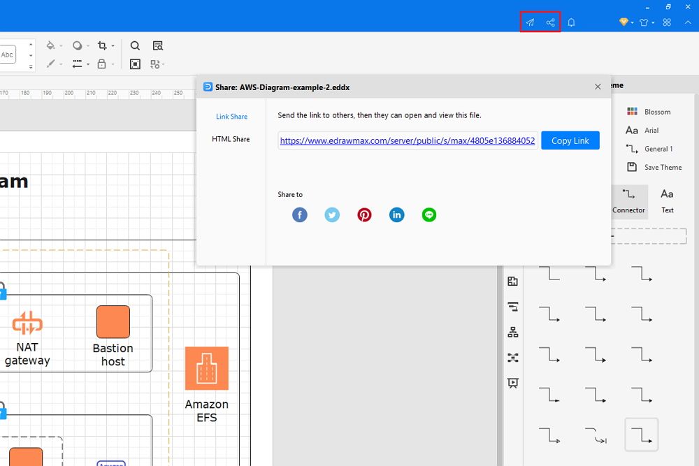
Step 5: Besides, you can share your UML deployment diagram with others via social media and web page. Or publish your UML deployment diagram in EdrawMax template gallery to show your work with others.
Part 3: UML Deployment Diagram Maker - EdrawMax
One of the most powerful programs that can compete with Microsoft Visio, EdrawMax is yet another diagramming software available for Windows, macOS, and Linux. The tool has several categories for almost all types of industries, and each category further has numerous templates to choose from, thus saving you a lot of time that you would otherwise waste in structuring a diagram, UML deployment diagram for this example, from scratch.
Price: free to use, lifetime plan for individuals, license for team and business.
EdrawMax
All-in-One Diagram Software
- Superior file compatibility: Import and export drawings to various file formats, such as Visio
- Cross-platform supported (Windows, Mac, Linux, Web, Android, iOS)
Part 4: UML Deployment Diagram Examples
Following are a few UML deployment diagram examples that would help you understand the diagram versatility.
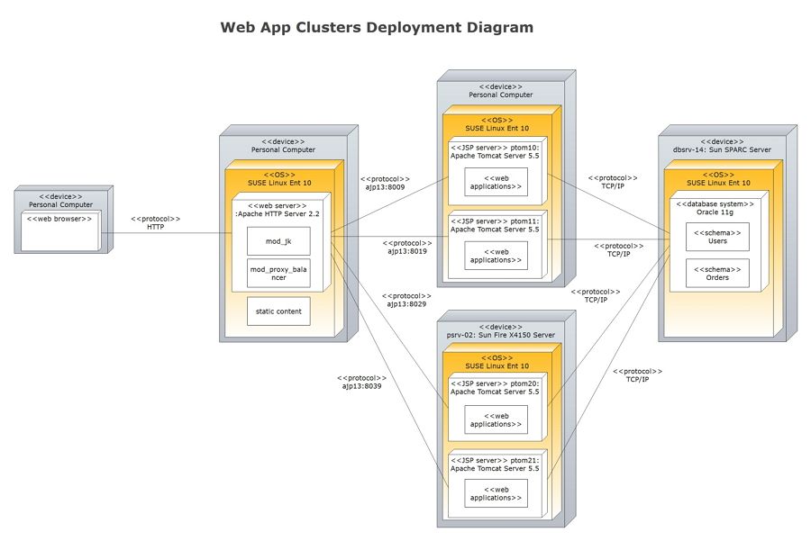
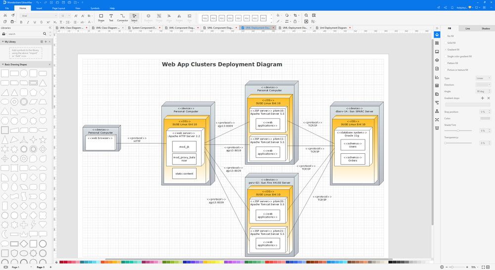
This deployment diagram illustrates how a J2EE web application functions with load balancing and clustering. It has the benefit of showing which specific servers are involved in each step of the process.
First, the Apache web server processes incoming HTTP requests. The web server then serves static content, such as HTML pages, images, CSS, and JavaScript. Requests to JSP pages are first load balanced, then forward to 2x2 Apache Tomcat servers via horizontal and vertical clustering.
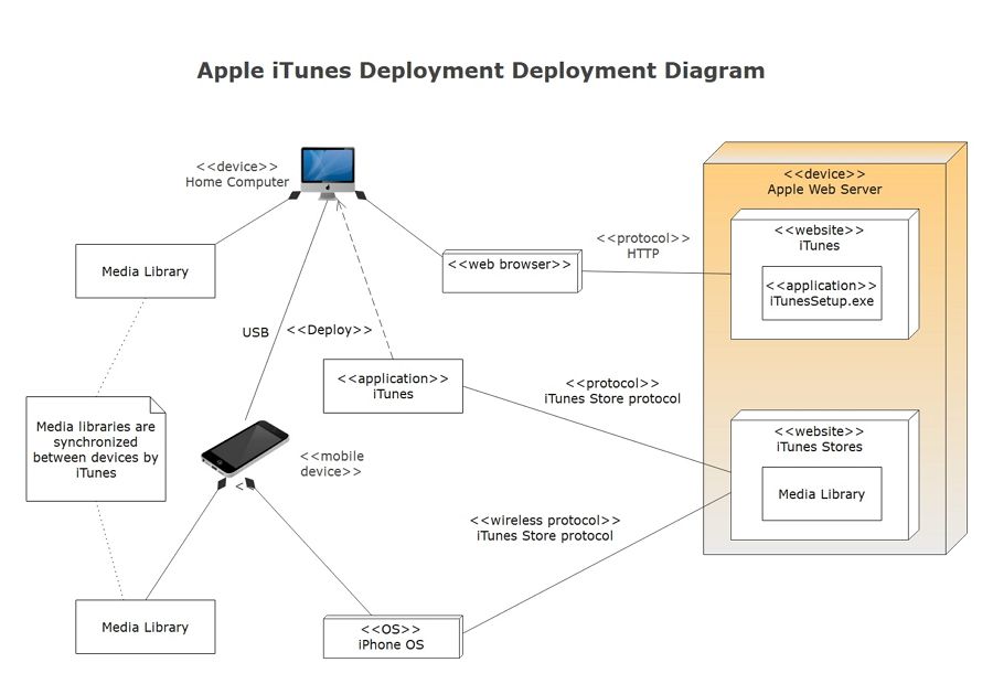
This deployment diagram is designed to show the functionality of Apple’s iTunes application, which can be downloaded from Apple’s website and installed on a computer.
Upon successful installation and registration, the iTunes application can communicate with Apple’s iTunes Store, where customers can purchase music, videos, and other online media.
Part 5: Conclusion
According to this article, there are mainly four parts to illustrate what is the UML deployment diagram, to tell you how to create a UML deployment diagram in EdrawMax, and to show you how easy and helpful EdrawMax tool is, then shows some UML class diagram examples. Creating a detailed UML class diagram with Edraw is an effective way to design and document a computer network, like the following illustration.
EdrawMax is an easiest all-in-one diagramming tool, you can create UML class diagrams and any other type diagrams with ease! With substantial UML class diagram symbols and cliparts, making UML class diagrams could be as simple as possible. Also, it supports to export your work in multiple formats and share your work with others. Get started to create your UML class diagram now!


