How to Create an Engineering Diagram Easily
Part 1: What is Engineering Diagram?
Engineering diagrams are used to convey technical information about an object. They include diagrams such as circuit diagrams, schematics, wiring plans, or floor plans. Multiple engineering diagrams are often required to specify enough information about a single component. They will often include detailed specifications about the materials used and quantities required.
Engineering diagrams are useful as they act as a blueprint for a project. They include all of the necessary specifications needed for architects, engineers and workers to complete the project accordingly. In addition, the recent explosion of computer-aided design makes these drawings more accurate and handy than ever before.
Part 2: How to Make an Engineering Diagram Effortlessly?
Step 1: Start EdrawMax.
Step 2: Navigate to [New]>[Electrical Engineering]
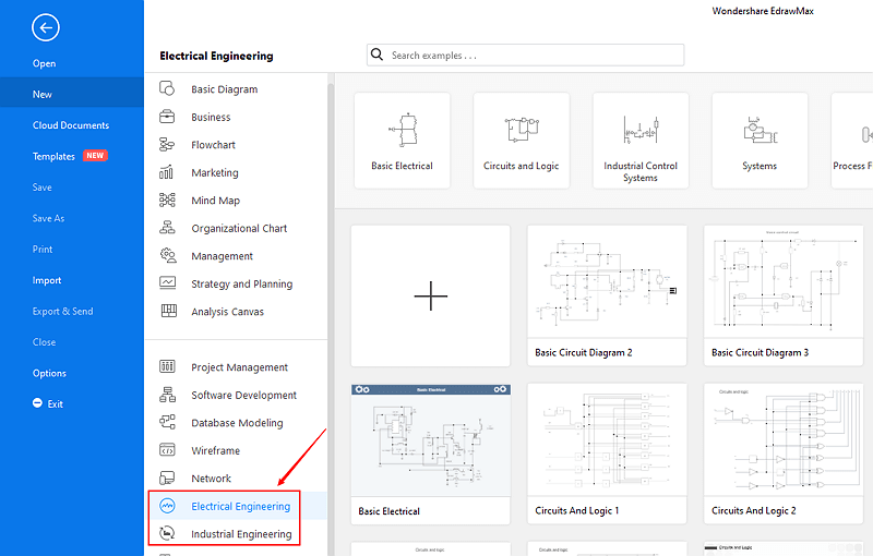
Step 3: Select one concept map template to edit on it or click the [+] sign to start from scratch.
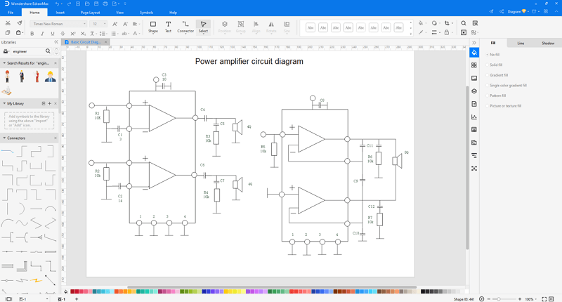
- Create Engineering Diagram - Basic Electrical Diagram: You may drag and drop the electrical symbols you need from the library which is on the left of the canvas. For drawing basic electrical diagram, we have basic electrical symbols, qualifying symbols, semiconductor devices, switches and relays, transmission path symbols. When you use the line/cable shape, you can find a floating button on the upper right of the shape. Click it, you can set the line/cable type as you like.
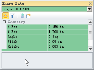
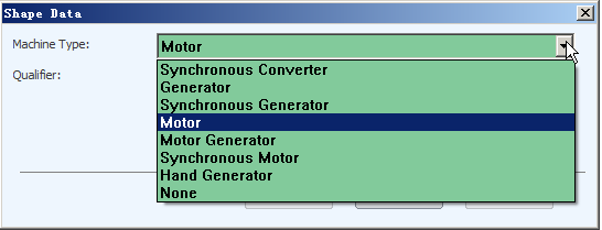
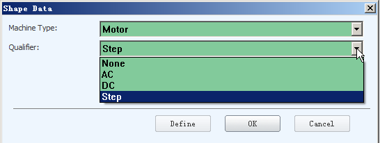
- Create Engineering Diagram - Circuits and Logic Diagram: When drawing circuits and logic diagram, you can simply drag and drop the circuits and logic symbols you like on the drawing page. When you use the "Terminal 3-phase" symbol, right click the shape on the drawing page, you will see a small window from which you can change the shape data. Click the shape data, you can see a small window appear from which you can change the relevant data.
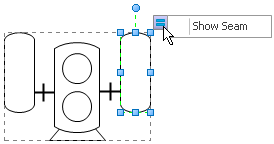
- Create Engineering Diagram - Industrial Control Systems Diagram: When drawing industrial control systems diagram, you need to pay attention that whether some symbols have floating buttons. If they do have such buttons, you can simply change some data to get the shape you want. When you drag and drop "step motor" shape on the drawing page, you will see the floating button on the upper right of the shape.
- Create Engineering Diagram - Piping and Instrumentation Diagram: When drawing piping and instrumentation diagram, you need to pay attention that whether some symbols have floating buttons. If they do have buttons, you can simply change some data to get the shape you want. For example, when you use the screw pump symbols and rotary compressor symbols, if you notice that they have floating buttons, it will be of great convenience when drawing the piping and instrumentation diagram.


Step 4: You can export the file to Graphics, PDF, editable MS Office file, SVG and Visio vsdx file.

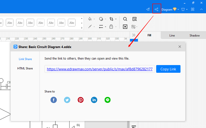
Step 5: And you can share your diagram with others via social media and online website page.
Part 3: Conclusion
According to this article, there are mainly two parts to illustrate what is engineering diagram and to tell you how to create an engineering diagram easily.
EdrawMax is an easiest all-in-one diagramming tool, you can create engineering diagrams and any other type diagrams with ease! With ready-made engineering diagram symbols and cliparts, making engineering diagrams could be as simple as possible. Also, it supports to export your work in multiple formats and share your work with others. Get started to create your engineering diagrams now!
EdrawMax
All-in-One Diagram Software
- Superior file compatibility: Import and export drawings to various file formats, such as Visio
- Cross-platform supported (Windows, Mac, Linux, Web)


