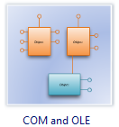
COM and OLE Diagram Software

It contains special shapes and settings for creating COM and OLE diagrams or diagrams of public exposed interfaces, COM interfaces, and OLE interfaces in object-oriented programming.
In Edraw Max, the COM and OLE template and shapes are in the Software folder.
Free Download Com and OLE Software and View All Examples
System Requirements
COM and OLE Software Features
- Predefined symbols: The vector stencils library COM and OLE contains various symbols of the Booch method. Supported by the drag-and-drop interface, users of all abilities can generate professional-looking COM and OLE diagrams.
- Quick-Start COM and OLE diagrams Templates: Professionally-designed COM and OLE diagram templates make you instantly productive.
- Wide Application: More than 200 kinds of diagrams can be made via Edraw diagramming package. Make customized infograpgics for your business documents, presentations and websites and so forth.
- Auto-formatting: Edraw can connect, align and distribute shapes automatically. The smart control handles help users make modifications more easily. The preset themes allow 1 click change of color, font, line and fill style.
- Free Support: Edraw team always stand by to solve your problem.
Who Needs to Use COM and OLE Diagrams?
- Software developers: Diagram publicly-exposed COM and OLE interfaces in object-oriented programming.
- Software designers: Show the relationship between COM objects and the interfaces they reference.
- Software program managers: Model the communication flow between OLE servers and containers.
COM and OLE Symbols
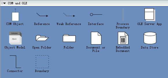
The COM and OLE template includes shapes for all the icons and symbols you can use to create COM and OLE diagrams. It also includes a variety of connector shapes you can choose to connect COM objects, object models, and other shapes.

COM and OLE
COM (Component Object Model) is a binary standard you can use to construct software applications from components written in different languages.
COM specifications regulate how the components are structured and how they operate with other components. The specifications govern:
- The structure of component interfaces.
- How components communicate, including across process and network boundaries.
- Shared memory management.
- The dynamic loading of components.
- Error and state reporting.
- How components and interfaces are uniquely identified.
OLE (Object Linking and Embedding) is a subset of COM functionality.
Create a COM Diagram
- On the File menu, point to New, point to Software, and then click Com and OLE.
- Drag a COM object shape onto the drawing page from COM and OLE.
- To change the style of the COM object shape, right-click the shape and choose COM Style.
- Name the COM object by selecting it, and then typing.
- Add interfaces to the COM object by dragging the control handle in the center of the shape.
- Name the interface by subselecting it and then typing.
- Note: All COM objects are created with one interface, IUnknown, by default.
|
Edraw Max is ideal for software engineers and software designers who need to draw detailed novel, small and exquisite software design documentation in the following UML diagram fields: |
|

