Difference between Schematics and Circuit Diagrams
Finding a tool to create Schematics Diagram and Circuit Diagram at the same time? Here is the one!
EdrawMax Diagram Maker gives you a way to create different diagrams with pre-made templates. You can simply design your work without effort. Just try it for free now!
In this article, you will learn the differences between schematic diagrams and circuit diagrams, and also know which one is more suitable under different circumstances. What's more, someone who wants to draw a schematic or circuit diagram will get an easy-to-use tool. Keep reading.
Differences between Schematic Diagrams and Circuit Diagrams
Schematics and circuit diagrams are commonly used in engineering diagrams. You may have heard them very often, but they vary each other slightly. Their targeted users or readers are different, where schematics are widely used among advanced schematics viewers while the circuit diagrams are friendly to beginners. With illustration of the differences between schematic diagrams and circuit diagrams, you will be clear about diagram uses in identifying the components of an electric system, tracing a circuit, or even fixing electrical equipment.
Schematic Diagram: Friendly to Advanced Users
A schematic, or schematic diagram, represents the elements of a system with abstract and graphic symbols instead of realistic pictures. A schematic diagram focuses more on comprehending and spreading information rather than doing physical operations. For this reason, a schematic usually omits details that are not relevant to the information that it intends to convey and may add simplified elements to help readers understand the features and relationships.
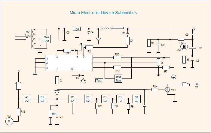
An electronic schematic to electronics is what a recipe is to a chef. It will tell you what ingredients to use and how to get the ingredients arranged and connected. Instead of explaining the recipe with details, a schematic diagram is used to depict the construction of electronics. Electronic schematics consist of digital electronic symbols that represent each of the components used. On the following microelectronic device schematic diagram, the symbols are connected with lines that show you how to connect the components.
Looking for a Tool to Create Electronic Schematic Diagram? Try Now!
EdrawMax Schematic Diagram Maker offers different kinds of diagrams and charts, such as schematic diagram, electrical schematic, arduino schematic, wiring schematic, schematic circuit diagram, etc... You can use pre-made templates to design your own chart! Free to try!
The schematic diagrams are also used in many other fields, not just in electrical systems. For example, when you take the subway, the subway map for passengers is a kind of schematic, and it represents subway stations with dots. The chemical process can also be displayed in a schematic diagram with symbols of chemical equipment.
Circuit Diagram: More Friendly to Beginners
A circuit diagram (also named electrical diagram, elementary diagram, and electronic schematic) is a graphical representation of an electrical circuit. Circuit diagrams are widely used for circuit design, construction, and maintenance of electrical and electronic equipment. Circuit diagrams can be divided into two categories - pictorial circuit diagram and schematic circuit diagram.
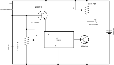
Pictorial diagrams are much easier to understand than schematic circuit diagrams. By connecting realistic electrical components with the wiring, a pictorial diagram makes it easy and quick for viewers to identify the electrical components of a system immediately without professional knowledge required. It can be commonly mentioned in user’s manual for normal operation. In some extent, circuit diagrams are more practical-applied.
Want to Draw Circuit Diagram in Few Minutes? Try This Out!
EdrawMax Circuit Diagram Maker offers multiple pre-made templates for you to edit, you can simply drag and drop the industry-standard symbols and use different colors to make customized circuit diagram in few minutes. Free to try!
What is a Schematic Circuit Diagram?
A schematic circuit diagram represents the electrical system in the form of a picture that shows the main features or relationships but not the details. In a schematic circuit diagram, the presentation of electrical components and wiring does not entirely correspond to the physical arrangements in the real device. If you want to understand a schematic diagram, you are required to master the basic knowledge of electricity and physics as well as internationally standardized symbols.
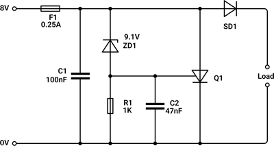
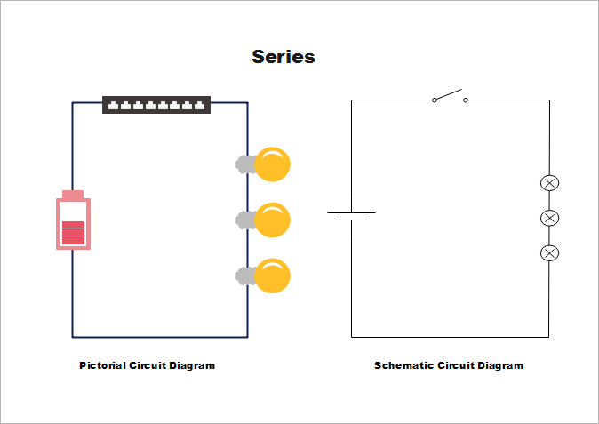
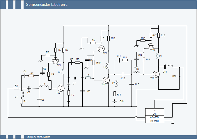
Look at the parallel circuits below, you may find that the battery is represented as two short lines, the lights are a circle with a cross inside, and the wiring is displayed as a line. Electrical engineers mainly use this kind of circuit diagram with unified circuit symbols. The following is a schematic circuit diagram of a semiconductor electronic.
Schematics and circuit diagrams are both important engineering diagrams. EdrawMax, all-in-one diagramming software, is an excellent schematics and circuit diagram maker. Free download the software to create your works.
Here to get a comprehensive diagram maker to create both schematic diagram and circuit diagram with ease!
EdrawMax
Efficient Diagram Maker >>
- Superior file compatibility: Import and export drawings to various file formats, such as Visio
- Cross-platform supported (Windows, Mac, Linux, Web)

