Jacobson's Use Case Diagram
Jacobson's Use Case Diagrams Software
Edraw contains special shapes and setting for creating jacobson's Use Case Diagrams. Use case diagrams illustrate how the outside world interacts with elements of the application system.
In Edraw Professional, the Jacobson's Use Case template and shapes are in the Software folder.
Free Download Jacobson User Case Software and View All Examples
System Requirements
Works on Windows 7, 8, 10, XP, Vista and Citrix
Works on 32 and 64 bit Windows
Works on Mac OS X 10.2 or later
Feature Comparison Between Visio and Edraw
| Features | Visio | Edraw |
| Predefined Symbols | Yes | Yes |
| Dynamic Help & Interface Labels | Yes | Yes |
| Embedded Config/Design Data | No | Yes |
| Created Automatically | No | Yes |
| On-Demand Mapping | No | Yes |
| Auto-Updating | No | Yes |
| Ready-made Templates | Yes | Yes |
| Easy to Use | No | Yes |
Who Can Use Them and How
- Software developers: Represent software applications using the Unified Modeling Language (UML) notation.
- Software developers: Illustrate and interpret software application relationships, actions, and connections.
- Program managers: Show high-level static software structures in presentations and specification documentation.
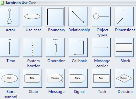
Jacobson's Use Case Symbols
Jacobson's Use Case Symbols include the Jacobson's analysis model and Jacobson's design model. Jacobson's analysis model defines three types of objects in a system: interface objects, entity objects, and control objects. Jacobson's design model shows how the system behaves. There are two types of diagrams under this model: interaction diagrams and state transition diagrams. Interaction diagrams are similar to UML's sequence diagrams. State transition diagrams are like UML state charts, but Jacobson also employs a number of unique symbols listed below.

Jacobson's Object-Oriented Software Engineering
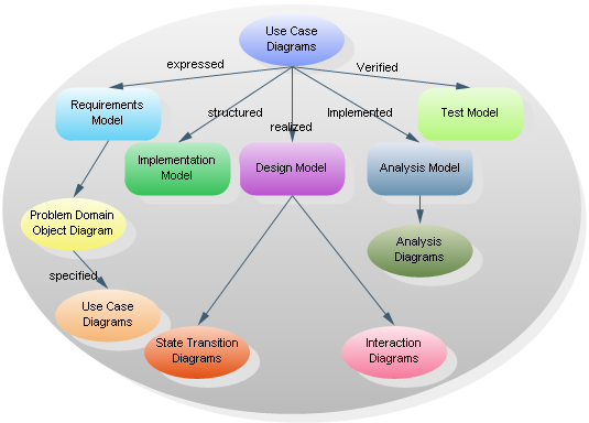
Ivar Jacobson's Object-Oriented Software Engineering (OOSE) is one of the precursors to the more modern Unified Modeling Language (UML). OOSE includes a requirements, an analysis, a design, an implementation, and a testing model. The relationship between the central use case diagram and the various models is illustrated below.

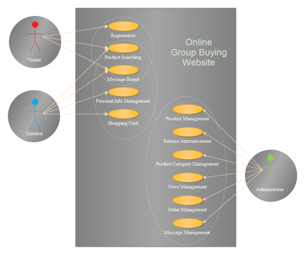
Use Case Diagram Example - Group Buying Website Use Case Diagram


