Logic Gate Symbols
A logic gate is an elementary building block of an electrical circuit. Most logic gates have two inputs and one output. Some circuits may have only a few logic gates, while others, such as microprocessors, may have millions of them. Read basic electrical symbol and electrical symbols introduction to get more information.
Logic Gate Symbols
Logic Gate Shapes
Logic shapes like And gate, Or gate, Not gate and more are included here.

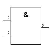
The picture below is a logic gate.

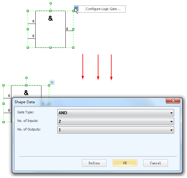
Most logic gates take an input of two binary values, and output a single value of a 1 or 0. To set the value you may select the symbol and click its floating button. Then choose the gate type, number of inputs and outputs.

Tri-state gate allows an output port to assume a high impedance state in addition to the 0 and 1 logic levels, effectively removing the output from the circuit.

And gate means it is True if both True.

Or gate means it is True if either True.

Not gate means it is True if input is False; False if input is True.X0R gate means True if either True, but False if both True.

NAND gate means False only if both True - AND followed by NOT.

NOR gate means True only if both False - OR followed by NOT.

XOR means the output is True if either, but not both, of the inputs are True.

XNOR gate means output is True if both True or both False - XOR followed by NOT.


