Types of Software Diagram - Overview
UML Model Diagram is ideal for software developers and program managers who need to illustrate and interpret software application relationships, actions, and connections using the Unified Modeling Language (UML) notation. It includes UML use case diagram, UML deployment diagram, UML component diagram, UML activity diagram, UML statechart diagram, UML sequence diagram, UML collaboration diagram, UML static structure diagram and UML package diagrams. View UML diagram samples.
Win 7 UI Design helps the software interface designer to create Windows 7 style software UI. Without programming skill requirement.
Booch OOD is also known as Object-Oriented Analysis and Design (OOAD), is a precursor to the Unified Modeling (UML).
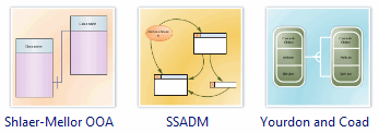
SSADM Diagram is another method dealing with information systems design. It was developed in the UK by CCT (Central Computer and Telecommunications Agency) in the early 1980s. It is the UK government's standard method for carrying out the systems analysis and design stages of an information technology project.
COM and OLE is used to create COM and OLE diagrams or diagrams of public exposed interfaces, COM interfaces, and OLE interfaces in object-oriented programming.
Data Flow Model Diagram is a significant modeling technique for analyzing and constructing information processes. DFD literally means an illustration that explains the course or movement of information in a process. DFD illustrates this flow of information in a process based on the inputs and outputs. A DFD can be referred to as a Process Model. View DFD diagram samples.
Enterprise Application is commonly used to design and document enterprise-wide system diagrams that include physical and logical components. Show software architecture or communication flow among assets enterprise-wide.
Jacobson Use Case is one of the precursors to the more modern Unified Modeling Language (UML). OOSE includes a requirements, an analysis, a design, an implementation, and a testing model.
Jackson Software Diagram refers to a method for structured programming based on correspondences between data stream structure and program structure. Jackson structured programming and data in terms of sequences, iterations and selections, and as a consequence it is applied when designing a program's detailed control structure.
Program Flowchart help programmers and software designers to depict all models and mappings related to a process.
NS Diagram is an alternative notation for process flowchart. A Nassi-Shneiderman (NS) diagram is a graphical method of stating algorithms. It is a diagrammatic approach to algorithm design but is not as bulky to draw as flowcharts.
Room Diagram is an object-oriented methodology for real-time systems developed originally at Bell-Northern Research. ROOM is based upon a principle of using the same model for all phases of the development process.
Program Structure Diagram is a graphic representation of an algorithm, often used in the design phase of programming to work out the logical flow of a program. It is used to create structural diagrams, flowcharts and memory diagrams.
Shlaer-Mellor OOA is considered an older technique that should be used on existing projects that have not migrated to UML.
Yourdon and Coad Diagram is an object-oriented method that precedes UML. Edraw contains special shapes and setting for creating Yourdon and Coad diagrams.


